Designing and Maintaining a Reliable Hazardous-Area H1 Segment with Eaton MTL5553
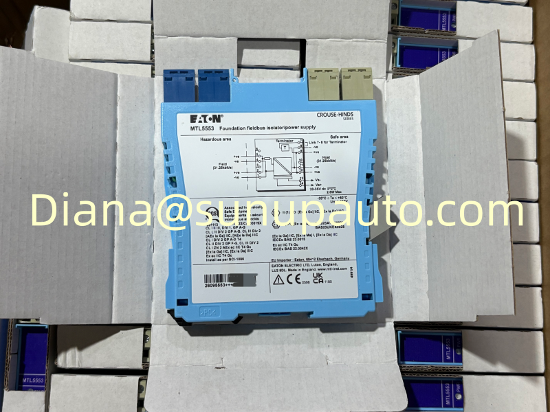
Eaton MTL5553 is an isolator and fieldbus power supply developed to extend a 31.25 kbit/s H1 network into a hazardous area while carrying both communication and operating power on the same pair of conductors. The module is relevant to FOUNDATION Fieldbus H1 projects where intrinsic safety, predictable segment voltage, digital communication quality, and practical cabinet maintenance must be considered together. Buyers searching for MTL5553 are usually matching an installed spare, expanding an existing segment, or replacing a module during a controlled shutdown, so the exact model number and surrounding segment design are important.
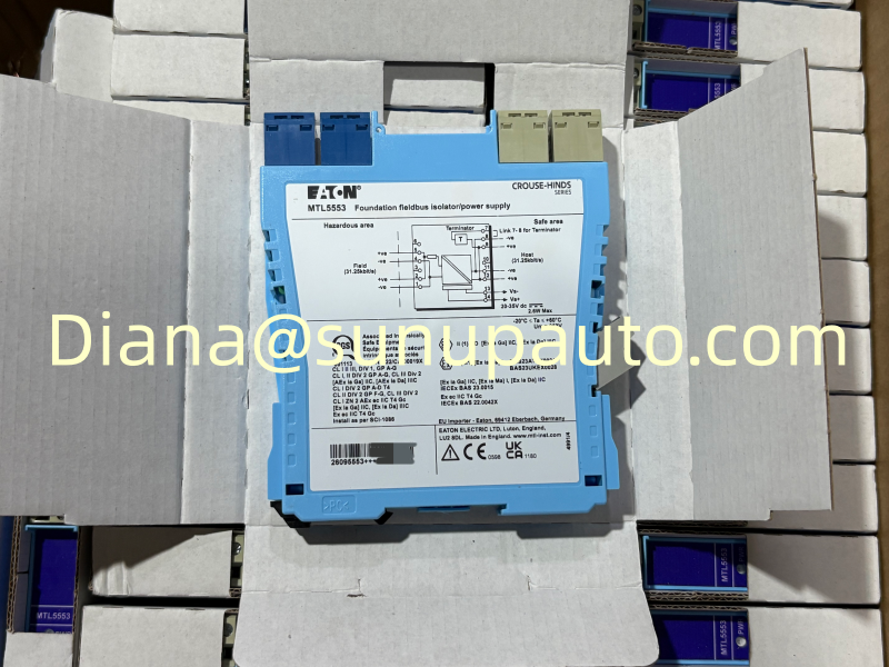
Where MTL5553 Sits in the Fieldbus Segment
A conventional analog loop serves one measured variable, but an H1 segment can connect several communicating devices to one shared trunk. MTL5553 forms the controlled interface between the safe-area host segment and the intrinsically safe hazardous-area portion. It passes the fieldbus signal and supplies restricted energy to field instruments that obtain power through the signal conductors.
Eaton identifies MTL5553 as compatible with 31.25 kbit/s fieldbus systems and as a Fieldbus Foundation specified Type 133 intrinsic-safety power supply. The hazardous-area output reference is 18.4 V plus or minus 2 percent, with 105 ohm DC impedance and a maximum current of 80 mA. These figures describe the module, but they do not replace a complete segment calculation. The final design must also account for field-device current, cable resistance, spur length, entity or FISCO requirements where applicable, terminators, temperature, and the permitted voltage at the most distant device.
The Terminator Decision Should Be Deliberate
A fieldbus segment normally requires the correct termination arrangement at the two intended ends of the communication path. MTL5553 includes an internal terminator that can be enabled for installations where the safe-area bus length is short. Enabling it simply because the link is available can create an extra terminator and weaken communication. Leaving it disabled when it is required can also produce reflections, unstable waveforms, and intermittent device visibility.
Before changing an installed MTL5553, record the existing terminator link, locate every other terminator on the segment, and compare the physical cable layout with the drawing. A maintenance technician should know whether the host-side terminator is in the power conditioner, a dedicated termination unit, the control-system interface, or the MTL5553 itself. After replacement, confirm device count and communication quality rather than judging the repair from the green power LED alone.
Voltage, Current, and Heat Need One Combined Review
The module accepts a 20 to 35 V DC supply. At an 80 mA output load, Eaton gives a typical supply requirement of 135 mA at 24 V and 105 mA at 35 V. Published internal power dissipation is approximately 2.3 W typical at 24 V and 2.6 W maximum at 35 V. These values matter when several MTL5553 modules are installed together because a cabinet can meet electrical loading requirements while still developing an unsuitable local temperature.
For normal heat dissipation, manufacturer guidance calls for installation on a horizontal DIN rail mounted on a vertical surface, with about 10 mm spacing between adjacent MTL5553 units. A non-optimum orientation can reduce the permitted maximum operating temperature. Check enclosure temperature at expected ambient conditions, especially where other power supplies or isolators share the same rail.
Commissioning the Segment as a Communication System
- Verify the label, terminal numbering, supply polarity, hazardous-area connection, safe-area connection, and screen-management arrangement.
- Confirm that the MTL5553 supply remains within its permitted range under maximum segment load and during any expected DC supply variation.
- Compare the total device current and cable voltage drop with the engineered segment calculation.
- Check the internal terminator selection against the actual location of both required segment terminators.
- Energize the segment and confirm that every intended field device appears at the host with the correct tag and address.
- Review communication diagnostics, retry counts, signal level, noise, and waveform quality with an appropriate fieldbus diagnostic tool.
- Test any handheld communicator connection provided through the optional HHC terminals without disturbing normal communication.
- Document supply voltage, hazardous-area output voltage, current demand, device count, terminator locations, and the final as-left condition.
Troubleshooting by Symptom
No devices visible: begin with DC supply, polarity, terminal assignment, open circuits, and terminator placement. Then isolate whether the problem is on the host side or hazardous-area side. A healthy power indication does not prove that the data pair is continuous or correctly terminated.
Devices appear and disappear: measure voltage at the far end, inspect loose terminals and shield connections, compare total current with the 80 mA limit, and look for an extra or missing terminator. Intermittent behavior can also be caused by moisture, damaged cable, a failing field device, or noise coupled from nearby power wiring.
Problems after replacement: compare the old and new MTL5553 link settings, supply voltage, rail orientation, spacing, and every conductor position. If the original fault remains, investigate the host interface, cable, spur protection, junction box, and field devices before replacing another module.
Information That Makes an MTL5553 Inquiry Useful
For quotation or spare-part confirmation, provide the full model MTL5553, required quantity, destination country, delivery deadline, and a clear product-label photo when possible. It is also helpful to state whether the request is for an emergency replacement, planned stock, or a new segment, and whether matching terminals, DIN-rail spacers, documentation, or related MTL fieldbus equipment are needed.
Sunup-MTL can assist with availability, packing, export documentation, and international delivery for MTL5553 and related industrial communication components. Final segment design, intrinsic-safety verification, certificates, cable parameters, device loading, installation, and commissioning must be reviewed by qualified personnel against the current project documents and manufacturer instructions.