Selecting, Earthing, and Commissioning Eaton MTL7787+ for Intrinsically Safe Analog Circuits
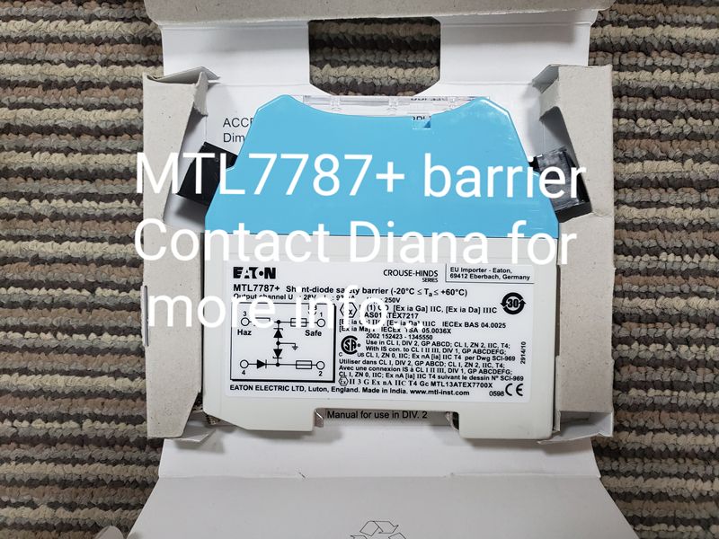
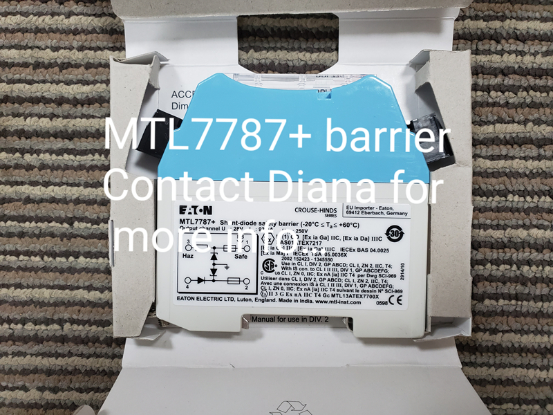
Eaton MTL7787+ is a positive-polarity shunt-diode safety barrier from the MTL7700 range. It is widely associated with intrinsically safe analog and digital circuits, especially 4-20 mA transmitter loops where the barrier must limit voltage and current entering the hazardous area. The model is rated at 28 V and 93 mA and mounts on DIN rail. Correct use of MTL7787+ depends on loop polarity, available transmitter voltage, a dependable intrinsic-safety earth, cable parameters, apparatus certification, and the complete entity assessment.
Why a Zener Barrier Depends on Its Earth Connection
A galvanic isolator separates circuits through transformer, optical, or other isolation techniques. A Zener barrier such as MTL7787+ uses shunt components and protective elements to divert excessive energy toward the designated earth path. The barrier can perform its protective role only when that path has the required integrity and low impedance. A loose, corroded, undersized, or incorrectly shared earth conductor can undermine the intrinsic-safety concept even when the barrier itself is undamaged.
The barrier rail and earth system should be designed, installed, inspected, and tested according to the applicable standards and manufacturer instructions. Keep the intrinsic-safety earth separate from unsuitable protective or signal references unless the approved design explicitly defines the connection. Record earth resistance or continuity test results and inspect mechanical connections during scheduled maintenance.
Positive Polarity Must Match the Real Loop
The plus symbol in MTL7787+ identifies the positive-polarity variant. It must match the direction of voltage and current in the selected circuit. A similar MTL7700 model with negative polarity, a different working voltage, or another resistance characteristic is not automatically interchangeable. Trace the loop from the safe-area supply through the receiving load, barrier terminals, field cable, and transmitter before selecting a replacement.
Eaton lists MTL7787+ as a recommended barrier for conventional and smart 4-20 mA two-wire transmitters when used with a suitable regulated supply. Manufacturer application data gives a reference of up to 13.02 V available for the transmitter and its lines at 20 mA while allowing 5 V across a typical 250-ohm safe-area load. The actual voltage margin must be recalculated using the plant supply tolerance, barrier characteristics, cable resistance at operating temperature, receiver load, protection devices, and the transmitter's minimum operating voltage.
Build the Loop Voltage Budget Before Installation
Start with the minimum safe-area supply rather than the nominal value. Subtract the required voltage across the control-system input or precision resistor, the barrier voltage drop at the maximum expected loop current, both conductor drops for the full cable route, terminal and protection-device losses, and the minimum voltage required by the field transmitter. A useful design retains margin for temperature, component tolerance, and future cable repairs.
If the calculation is marginal, do not assume the loop will be stable because it works at 12 mA on a workshop bench. A real transmitter may require more voltage during startup or at 20 mA, and cable resistance rises with temperature. HART communication, where used, also depends on a suitable load and signal path. Confirm the complete operating range and communication performance at the installed cable length.
Entity Parameters and Cable Energy Are Part of the Same Check
Intrinsic-safety approval requires more than matching a hazardous-area label. Compare the MTL7787+ output safety parameters with the permitted input parameters of the connected certified apparatus. Add cable capacitance and inductance using the actual length and cable data, then confirm the total remains within the allowable limits for the selected gas or dust group. Review ambient temperature, temperature class, zone or division, and any special conditions on the certificates.
Where simple apparatus such as contacts, thermocouples, or resistive sensors is connected, document why it qualifies and how its stored energy has been considered. Where a certified transmitter is used, keep the current certificate and control drawing with the loop file. Do not rely on a generic family certificate when the exact suffix or approval variation affects the design.
Installation Review at the DIN Rail
- Verify that the received label reads MTL7787+ and confirm positive polarity, 28 V reference, and the required approval markings.
- Inspect the DIN rail, barrier mounting foot, terminals, earth hardware, and segregation between hazardous-area and safe-area wiring.
- Confirm terminal numbers and conductor polarity against the approved loop drawing before energizing.
- Measure the intrinsic-safety earth continuity using the plant's approved method and record the result.
- Energize the loop through the correct protection and measure transmitter voltage at low and high current.
- Compare the safe-area current indication with a calibrated loop measurement at several points.
- Where HART is used, check device communication from the intended maintenance connection.
- Restore covers and labels, verify segregation, and update the as-built loop record.
Diagnosing a Weak or Dead 4-20 mA Loop
A zero-current loop may result from reversed polarity, an open fuse, loose terminal, broken cable, failed transmitter, missing supply, or incorrect barrier connection. Measure systematically from the safe-area supply toward the field rather than replacing MTL7787+ immediately. If the loop current saturates below 20 mA, calculate the voltage remaining at the transmitter and inspect cable resistance and receiving load.
Physical damage or repeated fuse operation suggests an abnormal overvoltage, wiring error, or earth problem that must be corrected before a new barrier is fitted. Eaton states that MTL7700 products are not user repairable; a damaged unit should be replaced with an equivalent certified product. Never bypass a barrier temporarily to restore production in a hazardous-area loop.
Ordering the Correct MTL7787+ Variant
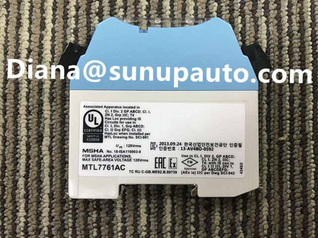
For a clear inquiry, provide the complete model MTL7787+ including the plus sign, quantity, destination, delivery deadline, and a readable label photograph. State whether the barrier serves a 4-20 mA transmitter, controller output, fire or gas device, contact, or another circuit, and include the installed rail or earth-accessory requirement when known. Similar MTL7700 numbers can differ in polarity, voltage, resistance, power handling, and application.
Sunup-MTL can assist with model checking, quotation, export packing, and international shipment for MTL7787+ and related MTL7700 barriers. Final selection, entity calculations, earth design, hazardous-area certification, installation, inspection, and maintenance must be completed by qualified personnel using current Eaton documentation and the approved project drawings.