

Precision Eaton MTL5582B Resistance Isolator for 2-, 3-, and 4-Wire RTD Signal Repetition in Hazardous-Area Systems
 October
12, 2026
October
12, 2026
Engineering Selection Guide for Eaton MTL5582B RTD Resistance Isolation, Wiring Flexibility, and Hazardous-Area Temperature Loops
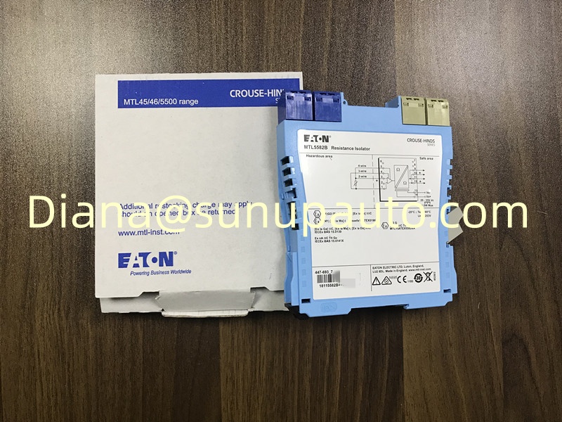
Eaton MTL5582B is a single-channel resistance isolator developed to repeat the resistance signal from an RTD or another compatible resistance device installed in a hazardous area. Instead of converting the sensor signal into a standard 4-20 mA output, MTL5582B reproduces the resistance for a monitoring system on the safe-area side. This makes the module especially relevant when an existing controller, indicator, or temperature input card is designed to receive a resistance signal directly.
The exact model number matters during replacement work. MTL5582B supports 2-wire, 3-wire, and 4-wire RTD arrangements, but the selected field wiring, safe-area wiring, resistance range, power supply, and certification requirements must all be checked against the installed loop. A label photograph and the original cabinet drawing are useful starting points for confirming the requested configuration.
Why Resistance Repetition Is Useful
Many temperature control systems are built around direct RTD measurement. In these installations, replacing the complete input architecture with a transmitter and current input may require wiring changes, new scaling, and additional engineering approval. MTL5582B allows the safe-area equipment to continue reading a resistance-based signal while the module provides galvanic isolation between the field circuit and the receiving system.
The unit is commonly associated with Pt100 applications, although the complete resistance range and sensor standard should be verified before ordering. Eaton specifies a 10 to 400 ohm output signal range and an RTD excitation current of 200 microamps. The response reaches within 4 percent of the final value within one second, which should be considered when the loop is used for monitoring, control, or alarm functions.
Key Engineering Data for Review
Single-channel resistance isolator for repeating RTD signals
Selectable 2-wire, 3-wire, or 4-wire hazardous-area connection
Safe-area wiring choice is independent of the field-side wiring mode
20 to 35 V DC supply with green power indication
Typical operating range from -20 to 60 degrees C
Nominal sensor-failure drive upscale to approximately 420 ohms
35 mm DIN-rail mounting in a slim 15.8 mm housing
These figures support preliminary model checking, but they do not replace the current Eaton datasheet, installation manual, safety instructions, or the project loop calculation. Entity parameters, cable characteristics, environmental limits, and local approval requirements still need engineering review.
Wiring Choices and Replacement Planning
A 2-wire RTD circuit includes lead resistance in the measured value, while 3-wire and 4-wire arrangements are used to reduce or compensate for lead effects. Before replacing MTL5582B, technicians should record the terminal numbers and conductor colors on both sides of the module. The safe-area connection does not have to use the same number of wires as the hazardous-area side, so copying only the visible field wiring may lead to an incorrect assumption about the output arrangement.
Open-circuit detection drives the output upscale. During commissioning, confirm how the receiving system interprets that condition and whether the resulting indication, alarm, or control action matches the plant philosophy. A controlled resistance simulation can help verify the complete loop without relying only on a room-temperature sensor reading.
A Practical Commissioning Sequence
Confirm the full MTL5582B catalog number and photograph the original terminals.
Verify the RTD type, normal resistance range, lead arrangement, and hazardous-area classification.
Check the 20 to 35 V DC supply before reconnecting the module.
Inspect DIN-rail mounting, terminal condition, conductor ferrules, and cabinet ventilation.
Apply known resistance values and compare the safe-area reading at low, middle, and high points.
Test an open-circuit condition and confirm the expected upscale response.
This sequence helps separate module behavior from sensor, cable, terminal, and input-card problems. When several loops show similar errors, investigate common power and environmental conditions before replacing multiple isolators.
Information to Include with an Inquiry
For an MTL5582B quotation, provide the required quantity, destination country, preferred delivery schedule, and product condition requirement. If the request is for a shutdown or urgent replacement, include a clear label photo and identify whether the installed sensor uses 2, 3, or 4 wires. Sunup-MTL can assist with model confirmation, stock communication, export packing, and combined sourcing for related MTL5500 interface modules.
Other hot sales models for your reference.
MTL5575, MTL5573, MTL5576-RTD, MTL5576-THC, MTL5581, MTL5582, MTL5541, MTL5544, MTL5546, MTL5546Y, MTL5511, MTL5514, MTL5517, MTL5521, MTL5524, MTL5525, MTL5531, MTL5532.
Latest News
-
Safety-Focused Pepperl+Fuchs KFD2-SH-Ex1.T.OP Switch Amplifier for SN/S1N Sensors, Active Voltage Output, and SIL 3 Loops…
October
12, 2026
-
Precision Eaton MTL5582B Resistance Isolator for 2-, 3-, and 4-Wire RTD Signal Repetition in Hazardous-Area Systems…
October
12, 2026
-
Compact Pepperl+Fuchs K-HM14 14-Pin HART Connection Cable for KFD2-HMM-16 and KFD0-HMS-16 Multiplexer Networks…
October
10, 2026