

Reliable Pepperl+Fuchs KFU8-DWB-1.D Rotation Speed Monitor for NAMUR Inputs, Overspeed Protection and DIN-Rail Control Panels
 September
21, 2026
September
21, 2026
Dependable Pepperl+Fuchs KFU8-DWB-1.D Frequency Monitoring for Conveyor, Pump, Fan, and Rotating Equipment Protection
Pepperl+Fuchs KFU8-DWB-1.D is a one-channel rotation speed monitor that evaluates pulses from a NAMUR sensor or mechanical contact. The module compares the measured input frequency with a programmed reference value and uses two relay outputs to signal overspeed, underspeed, or line fault conditions. Its wide frequency range, configurable start-up override, front keypad, and universal AC/DC supply make KFU8-DWB-1.D suitable for many industrial machines where dependable speed supervision is more important than a simple run indication.
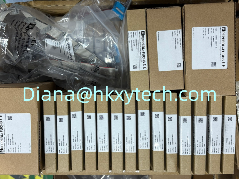
A Typical Maintenance Scenario
A conveyor motor is energized, but material begins to accumulate because the driven shaft is not turning at the expected speed. A motor auxiliary contact would still show that the starter is on, while KFU8-DWB-1.D can evaluate the actual pulse frequency from a sensor mounted at the shaft. If the speed remains below the configured limit after the start-up period, the relay can generate an alarm or initiate an approved protective action.
The same principle can be used for belt-slip detection, fan-speed supervision, pump-shaft monitoring, mixer rotation, screw-conveyor operation, centrifuge limits, bucket elevators, and other equipment where a pulse train represents mechanical movement. Depending on the application, the important condition may be underspeed, standstill, overspeed, or movement outside a defined operating band.
Core Operating Data
One digital input for a NAMUR sensor or dry mechanical contact.
Input frequency range from 1 mHz to 12 kHz.
Two relay contact outputs for alarm or control-system signaling.
Line fault detection with red LED and relay indication.
Start-up override programmable for as long as 1,000 seconds.
Front keypad and LC display for local configuration and indication.
Supply range of 20 to 90 V DC or 48 to 253 V AC, 50 to 60 Hz.
Functional-safety capability up to SIL 2 when applied according to the relevant requirements.
The broad input-frequency range allows KFU8-DWB-1.D to work with very slow movements as well as higher-speed pulse signals. The engineering relationship between shaft speed and frequency depends on the number of sensor targets or pulses per revolution. That conversion should be documented so future maintenance personnel can understand the configured reference value.
Start-Up Override Prevents Premature Trips
Many machines need time to accelerate from rest. Without a start-up override, an underspeed monitor could signal a fault immediately after the motor starts. KFU8-DWB-1.D can hold the relay outputs in user-programmed default conditions for a defined period of up to 1,000 seconds. The delay should be long enough for normal acceleration but short enough to detect a failed start promptly.
Set the override from actual machine-start data rather than guesswork. Record acceleration time under normal load, cold conditions, and other relevant operating states. If the machine takes longer to reach speed over time, investigate mechanical loading, belt tension, lubrication, drive condition, or process buildup instead of repeatedly extending the override.
Sensor and Wiring Review
The quality of the speed signal begins at the sensor. Check target size, sensing distance, alignment, mounting rigidity, cable route, pulse spacing, and maximum frequency. A NAMUR sensor provides defined current levels that support line fault detection, while a mechanical contact may require careful attention to contact bounce and switching frequency. The selected input mode and terminal connections must match the actual field device.
Route the sensor cable away from variable-frequency-drive output wiring and other high-noise conductors. Confirm shielding and grounding according to the project standard. During troubleshooting, observe the input pulse indication and compare the displayed frequency with an independent speed measurement where practical.
Commissioning Steps
Verify the exact KFU8-DWB-1.D model, supply voltage, input device, and relay wiring.
Calculate the expected input frequency from normal machine speed and pulses per revolution.
Enter the overspeed or underspeed reference and choose the required relay operating logic.
Set a justified start-up override based on the machine acceleration time.
Test normal running, stopped condition, sensor disconnection, sensor short circuit, and the required alarm response.
Record all settings, measured frequencies, relay states, and final test results.
Where KFU8-DWB-1.D participates in a safety-related function, proof-test intervals, fault response, diagnostics, architecture, and SIL calculations must be defined by qualified personnel. The module's capability does not by itself establish the SIL of the complete safety function.
Ordering and Replacement Notes
For replacement requests, send a clear photograph of the original KFU8-DWB-1.D label and record the existing settings before removing the module. Confirm the quantity, destination, required delivery date, supply type, sensor type, expected frequency, and relay function. On receipt, inspect the terminals and housing, verify the complete model, and complete a controlled functional test before returning the machine to service.
Other hot sales models for your reference.
KFU8-DW-1.D, KFU8-CRG2-1.D, KFU8-CRG2-Ex1.D, KFU8-GUT-Ex1.D, KFU8-UFC-1.D, KFU8-UFT-Ex2.D, KFD2-DWB-Ex1.D, KFD2-STC5-Ex2, KFD2-ST3-Ex2, KFD2-SR-Ex1.4S.LK, KFD2-RSH-1.2E.L3, KFD2-HMM-16, KFD0-HMS-16, KCD2-UT2-Ex1, KCD2-STC-Ex1.ES, KCD2-SR-Ex1.LB, and KFD0-CS-Ex1.51P.
Latest News
-
Reliable Pepperl+Fuchs KFU8-DWB-1.D Rotation Speed Monitor for NAMUR Inputs, Overspeed Protection and DIN-Rail Control Panels…
September
21, 2026
-
Versatile Pepperl+Fuchs KFU8-CRG2-1.D Transmitter Power Supply with Analog Output, Dual Relay Alarms and 20-Point Linearization…
September
21, 2026
-
Durable Pepperl+Fuchs NEN10-12GM50-E2 Inductive Proximity Sensor with 10 mm Non-Flush Sensing, PNP Normally Open Output and 2 m PUR Cable…
September
20, 2026