Eaton MTL4511 Digital Input Isolator for Reliable NAMUR Sensor and Dry-Contact Status Transfer
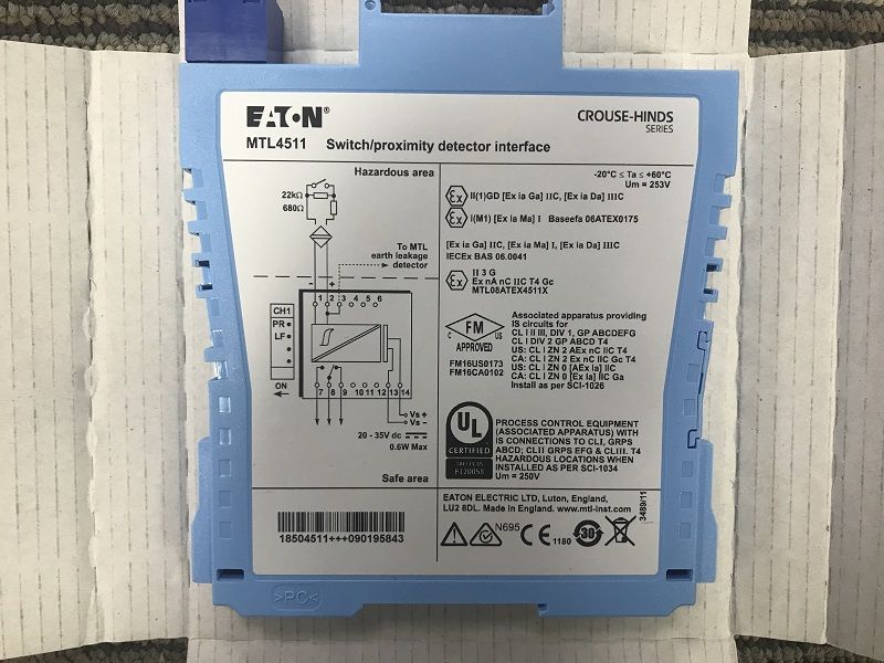
Eaton MTL4511 is a single-channel MTL4500 backplane-mounted isolator designed to connect a hazardous-area switch or proximity detector with a safe-area control system. It supplies a defined sensor circuit, evaluates the field current, provides a changeover relay output, and can supervise the field wiring for open- or short-circuit faults. MTL4511 is often selected for limit switches, valve-position feedback, tank-level contacts, machine status, and other discrete signals where clear separation between field and control circuits is required.
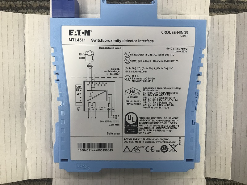
How MTL4511 Interprets the Field Signal
A NAMUR proximity sensor changes its current according to target position. MTL4511 monitors that current and changes the safe-area relay state when the input crosses the switching thresholds. Eaton publishes an output-open condition below 1.2 mA and an output-closed condition above 2.1 mA, with nominal hysteresis that helps prevent relay chatter near the decision point. A dry contact can also be used when the approved wiring arrangement includes the resistive network needed for line-fault monitoring.
The relay response is fast enough for normal status and interlock duties, with a published maximum response time of 10 ms. The actual process response also depends on the sensor, mechanical movement, field cable, control-system scan time, and any logic delay. MTL4511 should therefore be considered as one element of the complete signal chain.
Front Indication Supports Faster Diagnosis
Three LED colors give technicians immediate information at the cabinet. Green indicates power, yellow identifies channel status, and red reports line-fault detection. When a control-system input disagrees with the physical device, these indicators help narrow the investigation. A correct field-status LED with an incorrect DCS indication points toward the relay output, backplane, system cable, or input card. A red fault LED directs attention to the field cable, sensor, terminal connection, or line-fault resistor arrangement.
Line fault detection is selected by switches on the side of MTL4511. Record those switch positions before removing an installed module. A replacement with different LFD settings can create unexpected alarms or hide a wiring fault even though the model number is correct.
Operating Profile for Model Checking
Signal and output: MTL4511 handles one digital input channel from a NAMUR proximity detector or an appropriately wired switch contact. On the safe-area side, it provides a changeover relay contact for transferring status to the control or shutdown system.
Power and operating reference: the module is supplied with 20 to 35 V DC through the MTL4500 backplane. Published reference values include approximately 25 mA current consumption and 0.6 W power dissipation at 24 V DC, with an ambient operating reference of -20 to +60 degrees C.
Functional-safety context: MTL4511 is associated with SIL 2 and SIL 3 applications when it is used within a correctly designed and assessed safety function. The complete loop, relay logic, proof-test interval, failure response, wiring, and final element must be reviewed; the module designation alone does not establish the achieved safety integrity level.
A Practical Fault-Finding Sequence
- Confirm that the installed label reads MTL4511 and that the module occupies the documented backplane position.
- Check the green power LED and verify the backplane supply is within the permitted range.
- Operate the field switch or move the sensor target while observing the yellow status LED.
- If the red LED is active, isolate the loop as required and inspect the sensor, cable, terminals, and fault-detection resistors.
- Measure the input current with an approved method and compare it with the published switching thresholds.
- Verify the relay output, backplane connection, system cable, and receiving digital-input channel.
- After repair, test normal operation, open-circuit detection, short-circuit detection, and the required fail-safe response.
Do not bridge terminals or disable diagnostics without an approved procedure. In safety-related service, bypasses and proof tests must be controlled, recorded, and removed before the loop returns to operation.
Replacement and Backplane Compatibility
MTL4511 mounts on an MTL4500 backplane rather than an individual DIN-rail socket. Before ordering, identify the backplane, channel position, safe-area connector arrangement, relay logic, and field-terminal assignment. Eaton identifies MTL4511 as a nearest equivalent for some earlier MTL4015 installations, but notes that the repeat-contact arrangement differs and that terminal connections require checking. A legacy replacement should therefore be reviewed from the wiring diagram, not assumed from the cross-reference alone.
For cabinet upgrades, confirm that the receiving system accepts the relay behavior and that the contact rating is appropriate. Published Zone 2 contact reference is 10 W, 0.5 A, 35 V DC; the connected circuit must remain within all relevant voltage, current, and power limits.
Application and Purchasing Information
MTL4511 can support valve open/closed feedback, pressure-switch status, high- and low-level contacts, conveyor position sensing, burner permissives, pump status, and other discrete functions in oil and gas, chemical, power, water, mining, marine, pharmaceutical, and manufacturing facilities. Its value is strongest where field wiring diagnostics and a physical relay interface are needed together.
For an MTL4511 quotation, provide the exact model, quantity, destination, delivery deadline, product condition requirement, and a clear photograph of the existing label. Include the backplane reference and note whether the channel is part of a safety function. On receipt, compare the label with the purchase order, inspect the housing and backplane connector, and keep the module protected from moisture and electrostatic discharge until installation. Final selection, wiring, functional-safety verification, and commissioning must follow current Eaton documentation and approved site procedures.
Proof Testing and Long-Term Spare Control
Where MTL4511 forms part of a protective or safety-related function, the proof test should demonstrate more than relay movement. The test needs to confirm the field device, wiring diagnostics, input thresholds, output contact, receiving system, alarm presentation, and final logic action. Record the test stimulus and expected response before work starts. If a fault is discovered, document whether it was detected automatically by line fault detection or only during the scheduled test; this information helps engineers review diagnostic coverage and test intervals.
A spare MTL4511 should be stored with a reference to the supported backplane and cabinet locations. Keep side-switch settings, wiring diagrams, and test procedures with the spare register. Periodically inspect packaging and environmental conditions, especially where humidity, dust, or vibration may affect stored electronics. When an installed module is removed, label its fault status clearly so it cannot be returned to service by mistake.
For multi-site organizations, use the complete MTL4511 code in inventory records rather than a general description such as digital barrier. Similar MTL4500 modules may share the same housing while using different channel counts, relay arrangements, phase logic, or line-fault behavior. Exact identification protects maintenance teams from a visually plausible but functionally incorrect substitution.