Building a High-Power, Serviceable Fieldbus Trunk Around Pepperl+Fuchs HCD2-FBPS-1.500
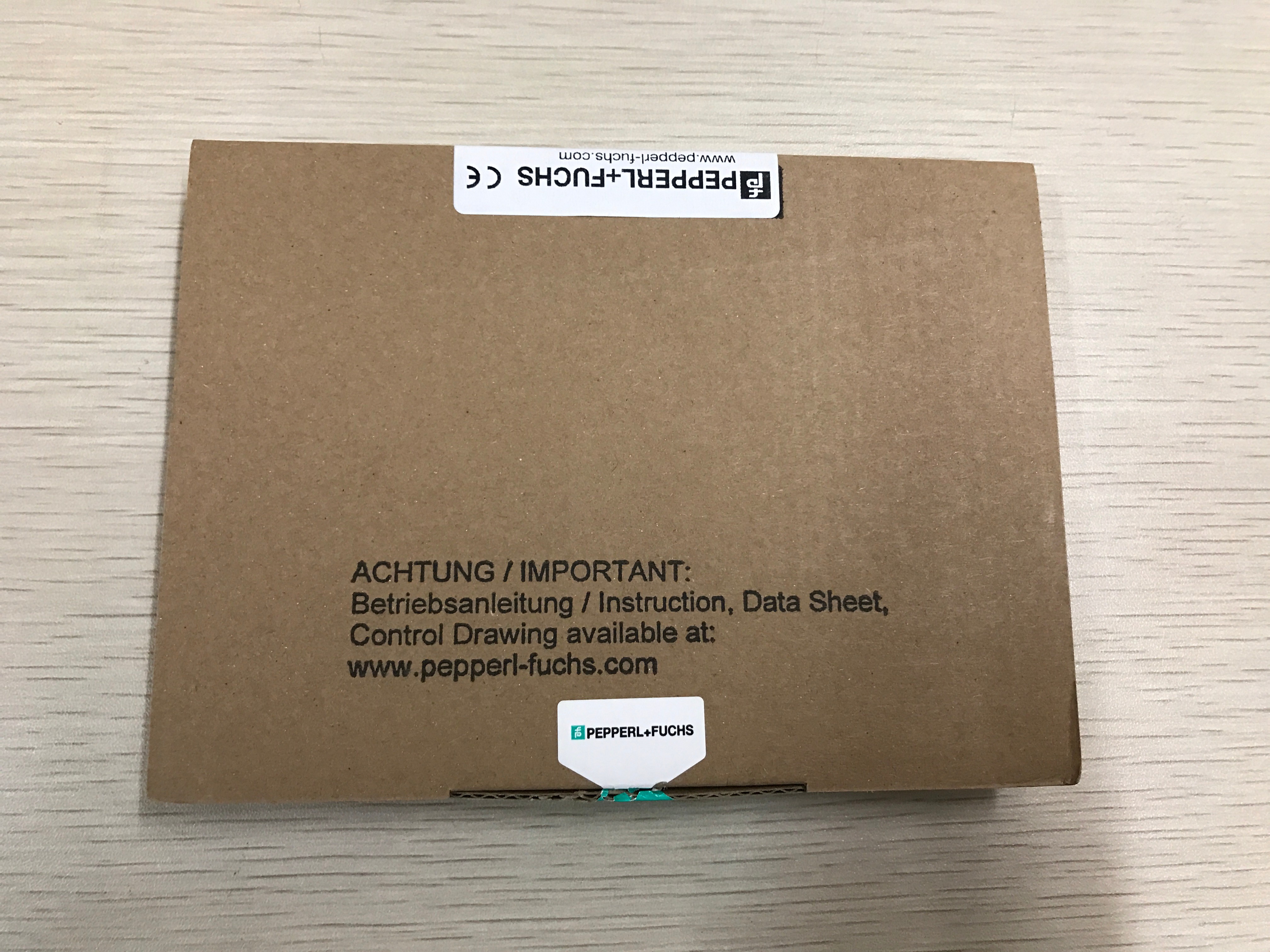
Pepperl+Fuchs HCD2-FBPS-1.500 is a motherboard-mounted FieldConnex fieldbus power-supply module for FOUNDATION Fieldbus H1 and PROFIBUS PA segments. It is designed to provide a high-power trunk for installations with substantial device loading or long cable routes, while maintaining galvanic isolation between the fieldbus segment and the DC supply. The module is also suited to redundant power-hub arrangements where serviceability, fault indication, packing density, and controlled module replacement are important.
A Power Hub Is Part of the Segment Architecture
HCD2-FBPS-1.500 should not be selected from current rating alone. A fieldbus segment combines DC power, a 31.25 kbit/s communication signal, cable impedance, terminators, spurs, field barriers or segment protectors, host interfaces, and multiple devices. The power hub conditions and feeds the trunk, but successful operation depends on the full arrangement. Designers should start with the required topology and device count, then check cable length, voltage drop, current demand, redundancy, hazardous-area installation method, and maintenance access.
Pepperl+Fuchs specifies a 28 to 30 V, 500 mA class output for HCD2-FBPS-1.500. The detailed fieldbus connection reference is 28 to 29.5 V, with a 550 mA short-circuit current. This capacity can support high device counts and long cable routes when the rest of the segment is designed accordingly. It does not mean that every segment may load the output to its maximum; connected equipment, cable temperature, spur protection, intrinsic-safety concept, and host requirements may impose lower limits.
Redundancy Must Remove a Real Single Point of Failure
HCD2-FBPS-1.500 can be hot swapped in a redundant configuration. This supports module replacement during operation when the approved motherboard and installation design provide a healthy parallel path. Redundancy should be tested as a function, not inferred from seeing two modules. Confirm independent feed protection, correct load sharing, alarm behavior, motherboard health, and the effect of losing either supply path.
A useful redundancy test begins with a stable, fully communicating segment. Record both supply indications and trunk voltage, then remove or isolate one approved path under controlled conditions. Verify that device communication and field voltage remain within limits and that the expected diagnostic appears. Restore the path, allow the system to stabilize, and repeat for the other module. Coordinate the test with operations because an error in the power architecture can interrupt every device on the segment.
LEDs Provide Fast Direction, Not a Complete Diagnosis
The green PWR indication is active when the output is above the specified threshold, while the red ERR indication flashes for an output short circuit or undervoltage condition. These LEDs help identify the starting point for troubleshooting, but they cannot confirm terminator placement, communication waveform quality, device address conflicts, or excessive noise.
When ERR flashes, isolate the problem systematically. Measure the DC input to HCD2-FBPS-1.500, inspect the motherboard and connectors, check trunk polarity, and disconnect downstream branches according to the approved procedure until the faulted section is identified. A damaged field cable, wet junction box, failed spur protector, reversed device, or overloaded segment can all appear as a power-supply fault. Replacing the module before locating the external cause may expose the spare to the same condition.
Power Budget and Thermal Review
The rated DC input range is 19.2 to 35 V. Pepperl+Fuchs lists typical module power dissipation around 1.6 W, supporting efficient high-density installation. Even with low individual loss, a power hub can contain several modules and operate inside a warm cabinet. Calculate total heat from all active and redundant components, check enclosure ventilation, and confirm the permitted ambient range at the real mounting position.
For the fieldbus side, prepare a worst-case voltage budget. Include maximum current for every device, startup behavior where relevant, trunk and spur resistance at operating temperature, connector losses, protection devices, and the minimum HCD2-FBPS-1.500 output under the selected conditions. Verify adequate voltage at the most distant device rather than relying only on the value measured at the power hub.
Galvanic isolation between the fieldbus segment and supply helps separate the communication network from the DC source, but it does not remove the need for an intentional grounding and shielding concept. Review the host, power hub, cable screen, surge protection, and field enclosure as one system. Unplanned screen connections at several locations can create circulating current, while a completely floating arrangement may not satisfy the project noise-control or protection strategy. Follow the approved segment drawing and record every intentional earth connection.
Commissioning Questions That Keep the Work Focused
- Is the correct FieldConnex motherboard installed and is its terminator arrangement understood?
- Does the HCD2-FBPS-1.500 input remain within 19.2 to 35 V under normal and degraded supply conditions?
- Is trunk voltage acceptable at the hub and at the electrically most distant field device?
- Do all intended devices remain online while each redundant module is tested separately?
- Are shield, grounding, and cable-separation practices consistent with the project fieldbus standard?
- Are PWR and ERR indications visible, labeled, and linked to a maintenance response?
- Have segment diagnostics been recorded for future comparison, including noise, signal level, retries, and device count?
Capture the results in the segment file together with the cable schedule, topology drawing, device list, terminator locations, motherboard part number, module positions, and redundancy test. This creates a useful baseline for later troubleshooting.
Planning a Replacement or New Supply
For replacement work, compare the full HCD2-FBPS-1.500 code, motherboard type, hardware revision, redundant arrangement, and fieldbus protocol. Photograph the installed label and connector area before removal. If the original module shows a short-circuit or undervoltage alarm, confirm that the downstream fault has been cleared before inserting the replacement.
For quotation, provide HCD2-FBPS-1.500, quantity, destination, delivery deadline, and whether matching motherboards, redundancy components, host interfaces, segment protectors, or documentation are required. Sunup-MTL can assist with product identification, quotation, packing, and international delivery. Final segment capacity, hazardous-area suitability, hot-swap procedure, certification, installation, and commissioning must be confirmed by qualified personnel using current Pepperl+Fuchs and project documentation.