
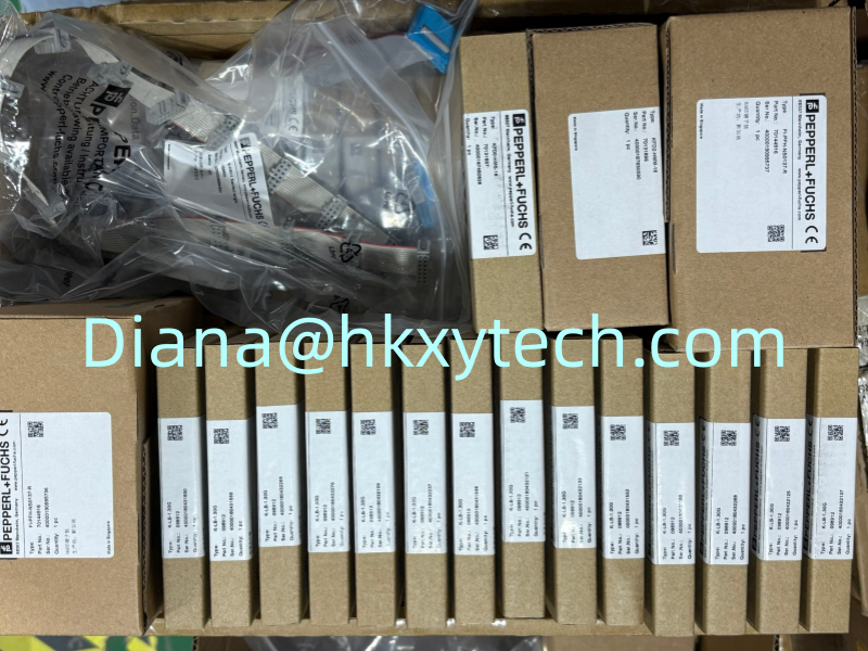
Pepperl+Fuchs NEN10-12GM50-E2 Long-Range M12 Inductive Sensor for Non-Contact Metal Detection
Pepperl+Fuchs NEN10-12GM50-E2 is a cylindrical inductive proximity sensor intended for non-contact detection of metal targets. Its M12 housing and increased nominal sensing distance make it suitable where a compact threaded sensor is required but a conventional short sensing range would leave too little installation tolerance. The E2 output version is commonly selected for three-wire DC, PNP normally open switching applications.
What the 10 mm Sensing Distance Means
NEN10-12GM50-E2 belongs to a sensor family with a rated operating distance of 10 mm when tested with the specified standard steel target. That figure is a nominal reference, not a guarantee that every target will switch at exactly 10 mm. The assured operating range is lower, and the effective distance changes with target material, size, alignment, temperature, mounting conditions, and surrounding metal.
Aluminum, copper, stainless steel, and brass produce different reduction factors compared with mild steel. A maintenance replacement should therefore be tested with the real machine target rather than positioned only by a ruler. If the existing sensor detects a small stainless-steel flag, moving the new NEN10-12GM50-E2 to the nominal steel distance may result in intermittent operation.
Non-Flush Installation Needs Free Space
The NEN10-12GM50-E2 family is described as non-flush or non-embeddable. The sensing face must project from surrounding metal, and adequate clearance is required around the active surface. Installing the sensor fully inside a steel bracket can reduce sensing performance or create false switching. The machine drawing should show the intended free zone, target travel, and protection against direct impact.
Use both mounting nuts and tighten them within the permitted torque for the M12 housing. The sensor should be mechanically secure but not distorted. If vibration is present, include suitable locking practice and route the cable so that movement is not transferred directly to the cable entry. Protect the sensing face from metal chips that could remain within the active field.
Electrical Characteristics for Control-System Matching
- Three-wire DC sensor with PNP normally open switching behavior for the E2 version.
- Nominal 10 mm non-flush sensing concept with an assured range below the nominal value.
- Typical operating supply range of 10-30 V DC for this sensor family.
- Switching frequency suitable for routine machine-position and presence-detection duties.
- Yellow LED indication for visual confirmation of switching state.
- Protection functions that include reverse-polarity, short-circuit, and overload protection.
- Industrial cylindrical housing with an IP67 protection concept when correctly installed.
Before wiring NEN10-12GM50-E2, confirm the control input is intended for a sourcing PNP signal. An NPN input arrangement will not become compatible through wire-color changes. Brown, blue, and black conductor functions should be confirmed from the exact datasheet and the installed cable version. Do not rely on a drawing for a connector version if the purchased product uses a fixed cable.
A Practical Setup Method
- Move the machine to a safe condition and identify the real target at the required detection point.
- Mount NEN10-12GM50-E2 with the specified non-flush clearance from surrounding metal.
- Connect the correct DC supply and PNP input according to the approved wiring diagram.
- Bring the target slowly into position and note the switch-on point from the sensor LED and PLC status.
- Move the target away and confirm the release point, allowing for normal hysteresis.
- Repeat the cycle at the minimum and maximum mechanical tolerances of the machine.
- Secure the sensor and cable, then record the final mounting distance for future maintenance.
This approach tests the complete application instead of only the sensor. Bracket movement, shaft play, conveyor vibration, temperature, and target shape can all affect the available operating margin. A reliable installation should switch well inside the usable range rather than at its limit.
Troubleshooting Intermittent Detection
If NEN10-12GM50-E2 switches inconsistently, first inspect the mechanical target path. Check for loose brackets, target runout, metal contamination, cable damage, and incorrect supply voltage. Confirm that the PLC input state follows the local LED. If the LED changes correctly but the controller does not, investigate field wiring and input-channel configuration. If neither changes, move a verified steel target toward the sensing face to separate an application-distance problem from an electrical failure.
When replacing another sensor, compare output polarity, normally open or normally closed action, sensing distance, flush or non-flush installation, cable or connector style, housing length, and environmental rating. A model with the same M12 thread can still have a completely different electrical function.
Preventive maintenance should include cleaning the sensing face, checking mounting-nut tightness, inspecting the cable entry, and observing the switching margin at normal machine speed. If the target only barely reaches the operating point, correct the bracket or target position before production vibration causes nuisance stops. Recording the final distance and LED state gives future technicians a useful baseline for evaluating NEN10-12GM50-E2 performance.
Typical Uses and Ordering Support
NEN10-12GM50-E2 may be applied to conveyor positioning, machine-part detection, packaging equipment, material handling, valve and actuator position feedback, speed targets, assembly fixtures, and general factory automation. The extended sensing concept is especially useful when a protective mechanical gap is desirable between the sensor face and moving metal.
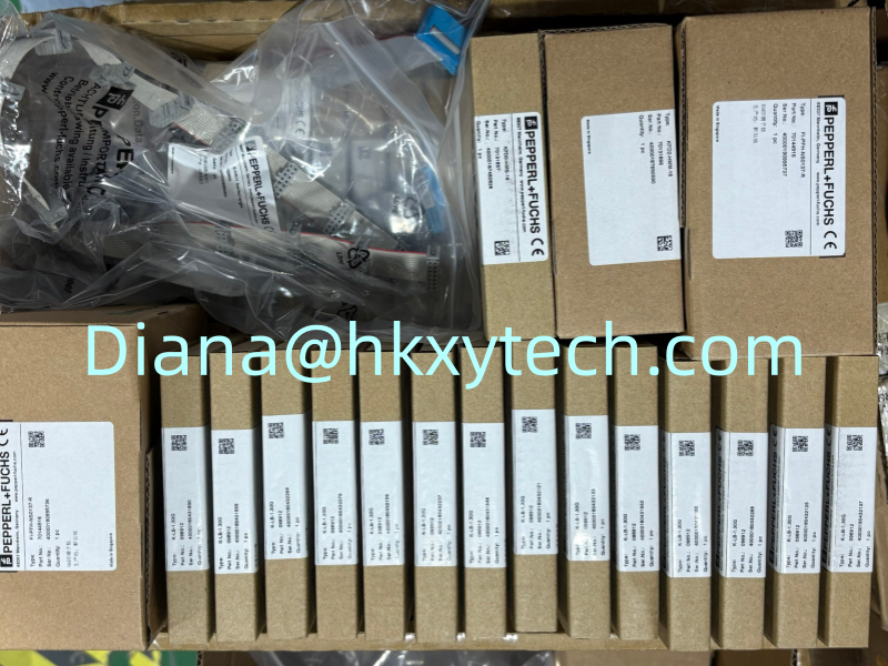
For a quotation, provide the full NEN10-12GM50-E2 code, quantity, destination, delivery requirement, and a label photograph if the request concerns an installed machine. State the target metal, wiring type, and whether a fixed cable or connector variant is required. Sunup-MTL can support model confirmation, competitive quotation, export packing, and international delivery for Pepperl+Fuchs sensors and related automation components. The final mounting and electrical design should follow the current exact-model documentation.