Pepperl+Fuchs KFD2-SOT2-Ex1.LB Application Note for Fast NAMUR Signal Transfer and Practical Fault Diagnostics
KFD2-SOT2-Ex1.LB is a one-channel Pepperl+Fuchs K-System switch amplifier that accepts a NAMUR sensor or mechanical contact from the field side and provides passive electronic outputs on the control side. Its fast switching capability, reversible operating mode, line-fault detection, LED indication, and Power Rail support make it a useful interface for discrete signals that must cross between hazardous and safe areas.
This is not simply a relay replacement. KFD2-SOT2-Ex1.LB has two passive transistor outputs with configurable behavior, and its line monitoring depends on the field circuit and switch settings. Correct selection therefore requires attention to the input device, controller input characteristics, output polarity arrangement, Power Rail design, and required fault response.
Signal Journey from the Field Device to the Controller
At the field terminals, KFD2-SOT2-Ex1.LB supplies the NAMUR sensing circuit and evaluates the resulting current. A proximity sensor or a correctly prepared mechanical contact changes between low- and high-current states. The switch amplifier interprets this state, isolates it from the control side, and changes its passive electronic output so a PLC or distributed control system can recognize the process condition.
The module also watches for current outside the normal NAMUR range when line-fault detection is enabled. A broken wire or short circuit can then be separated from an ordinary process state. This distinction is valuable in applications where a stopped conveyor, closed valve, or absent target must not be confused with damaged field wiring.
Output I, Output II, and the Role of the DIP Switches
Output I is the primary signal output. Output II can repeat the switching state or be assigned as a fault indication, depending on the selected configuration. DIP switches on the front set the operating direction, the assignment of the second output, and whether line-fault detection is active. The factory setting should never be assumed to match an existing cabinet without checking the loop documentation.
Reversible operating direction lets the user decide whether a high or low input current produces the active output state. This flexibility supports different fail-state philosophies, but it also creates a commissioning responsibility. Record the switch positions before removing the old KFD2-SOT2-Ex1.LB and compare them with the replacement before power is restored.
Electrical Data That Shapes the Interface
- Nominal 24 V DC operation, with the published supply range of 20-30 V DC
- NAMUR input at terminals 1+, 2+, and 3- with approximately 8 V open-circuit reference
- Line break detection at very low input current and short-circuit detection above the stated threshold
- Two passive transistor outputs rated up to 30 V and 100 mA under the specified conditions
- Switching frequency up to 5 kHz for faster discrete signal applications
- Power Rail collective error messaging for organized cabinet diagnostics
The passive outputs need an external control-side voltage and a compatible receiving input. They should not be treated as powered voltage sources. Check the PLC input voltage, current, common reference, and off-state leakage requirement before connection. If Output II is used for fault indication, make sure the control logic distinguishes that channel from the normal process signal.
Where Fast Switching Can Be Useful
The 5 kHz maximum switching frequency allows KFD2-SOT2-Ex1.LB to serve more than slow limit-switch duties. It may be considered for pulse detection, speed monitoring inputs, turbine or rotating-equipment pickups, and other NAMUR signal sources where both isolation and faster response are needed. The entire chain must still support the required frequency, including the sensor, cabling, transistor output, controller hardware, and software scan time.
For ordinary valve position, tank switch, or proximity detection, the faster capability provides margin but does not replace good noise control. Route field cables appropriately, terminate shields according to the project standard, and avoid running sensitive signal cables beside high-energy switching conductors.
A Practical Replacement Sequence
- Identify the channel and place the process in a safe maintenance condition
- Photograph the existing KFD2-SOT2-Ex1.LB label, terminals, and DIP-switch positions
- Confirm whether power comes from the Power Rail or direct terminals 14+ and 15-
- Tag every conductor and verify that the field input uses the correct terminal arrangement
- Install the replacement on the 35 mm DIN rail and restore the documented settings
- Test normal switching, lead break, and short-circuit indication where site procedures permit
- Verify both transistor outputs and the controller alarm logic before returning the loop to service
This sequence is deliberately broader than swapping one module. The most common commissioning delays come from undocumented switch settings, unexpected output assignment, or an existing field fault that becomes visible only after a healthy replacement is installed.
Mechanical and Cabinet Considerations
KFD2-SOT2-Ex1.LB uses a narrow K-System housing approximately 20 mm wide and mounts on a 35 mm DIN rail. Removable terminals simplify service, but plug identity and orientation must be preserved. Inspect the blue field-side and green control-side terminal blocks for loose screws, damaged coding, and contamination before reusing them.
The published degree of protection is IP20, so the module belongs inside a suitable enclosure. Maintain cabinet temperature within the specified range, allow airflow around densely populated rows, and review total Power Rail loading. A stable 24 V supply and clean grounding arrangement support dependable switching and diagnostic behavior.
Questions to Resolve Before Ordering
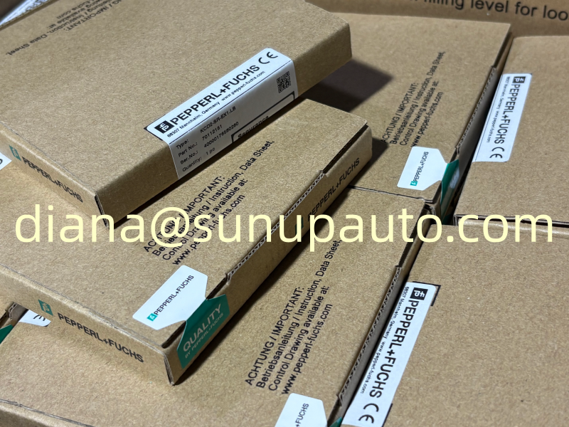
Is the field device a NAMUR sensor or a dry contact? Is line-fault monitoring required, and does a dry-contact circuit include the appropriate resistor arrangement? Should Output II mirror the signal or report a fault? Does the controller input accept a passive transistor output at the available voltage? Is the collective error bus used on the Power Rail? These questions define the application more clearly than the housing photograph alone.
If the original module is marked KFD2-SOT-Ex1 or KHD2-SOT-Ex1, manufacturer documentation identifies KFD2-SOT2-Ex1.LB as a related replacement model, but the actual wiring and functional requirements should still be reviewed. Historic cabinets may contain project-specific connections that are not obvious from the model name.
Supply and Model-Confirmation Support
Sunup-MTL can assist with KFD2-SOT2-Ex1.LB inquiries for maintenance spares, panel refurbishment, new projects, and distributor stock. Send the exact model, quantity, destination, and required delivery time. A clear label photo and a note describing the input sensor and output assignment can speed up confirmation.
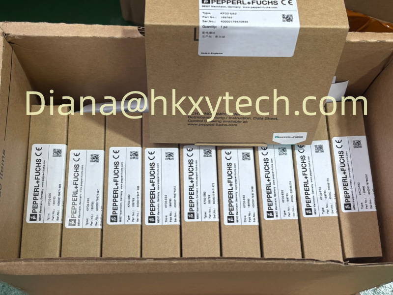
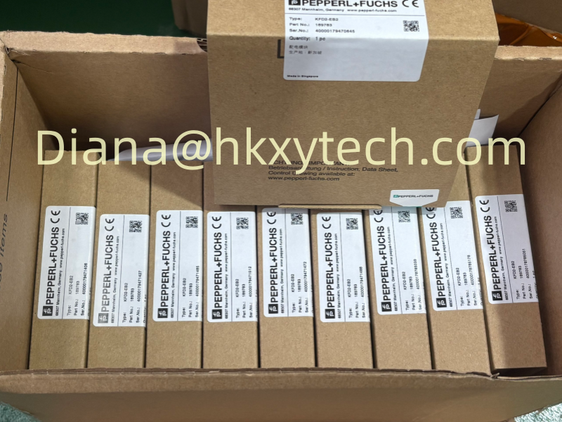
Related requests may include Pepperl+Fuchs Power Rail components, KFD2-EB2 power feed modules, NAMUR sensors, isolated switch amplifiers, and signal conditioners. Combining the full cabinet list in one inquiry helps check model consistency and organize shipment for international delivery.