Application and Maintenance Guide for the Pepperl+Fuchs NBB20-L3M-US-C3-V12 Inductive Sensor
Pepperl+Fuchs NBB20-L3M-US-C3-V12 is a weld-immune inductive proximity sensor with a 20 mm rated operating distance, flush mounting, two-wire AC/DC normally open output, durable metal construction, and a three-pin V12 connector. It is intended for non-contact detection of metallic targets in industrial machinery where conventional sensors may be exposed to welding fields, metal contamination, mechanical impact, washdown, or repeated alignment work. Reliable performance depends on target material, mounting geometry, electrical load, connector quality, and the actual distance between the target and sensing face.
What a 20 mm Rated Distance Means in Practice
The published rated operating distance is 20 mm, but it should not be used as the normal mechanical set point. Pepperl+Fuchs gives an assured operating range from 0 to 16.2 mm and an actual operating-distance range from 18 to 22 mm under reference conditions. Production tolerances, target material, temperature, supply voltage, contamination, mounting, and mechanical movement can change the switching point.
Set the target inside the assured operating range with enough reserve for vibration, bearing movement, thermal expansion, conveyor tracking, and installation tolerance. A sensor adjusted at the outer edge of detection may pass a stationary commissioning test and then chatter during real operation. Record the measured on and off positions rather than writing only “sensor adjusted.”
Target Metal Changes the Effective Range
Inductive sensor distances are normally referenced to a standard steel target. NBB20-L3M-US-C3-V12 has reduction factors for other metals. Pepperl+Fuchs lists an aluminium factor around 0.30 to 0.40 and a stainless-steel 304 factor around 0.60 to 0.80. A target that switches at a comfortable distance when made from steel may require much closer positioning after a machine component changes to aluminium or stainless steel.
Target size and orientation also matter. A small bolt head, curved surface, thin plate, or angled flag may produce less coupling than a large flat target. Keep the target face parallel to the sensing face where possible and ensure the moving part cannot strike the sensor under worst-case travel, wear, or maintenance adjustment.
Flush Mounting Still Requires Mechanical Discipline
The sensor is designed for flush installation, allowing the sensing face to sit within the specified metal mounting environment. Follow the dimensional drawing and avoid placing additional metal in front of the active face. Use the modular bracket or a rigid equivalent that resists movement. Tighten hardware evenly and do not use the connector or cable as a mechanical restraint.
The zinc housing and base are PTFE coated, and the sensing face uses thermoset plastic. The assembly is rated IP67 when correctly installed with a suitable connector. Inspect the sensing face for impact marks, weld spatter, abrasion, and coating damage. Check the connector seal, cable jacket, strain relief, and mounting base during preventive maintenance, especially in washdown or outdoor locations.
Weld Immunity Supports the Application but Does Not Replace Good Installation
NBB20-L3M-US-C3-V12 is designed for weld-immune service, making it relevant to body shops, fixtures, clamps, transfer systems, and fabricated-metal handling equipment. Weld immunity reduces susceptibility to strong electromagnetic fields associated with welding, but cable routing, grounding, connector condition, and separation from high-current conductors remain important.
Route the sensor cable away from welding leads where practical and avoid large loops that can pick up interference. Secure the cable so repeated robot or fixture movement does not flex the connector. If false switching occurs only during a welding cycle, compare sensor indication, controller input, supply voltage, cable route, and grounding timing. This separates electromagnetic disturbance from vibration or target movement.
Understanding the Two-Wire AC/DC Interface
This model uses a two-wire normally open AC/DC output. Pepperl+Fuchs lists a rated operating voltage of 24 to 250 V DC or 24 to 230 V AC, with a wider operating-voltage reference of 20 to 300 V DC or 20 to 253 V AC. The intended controller, relay, or contactor input must be compatible with a two-wire electronic sensor, including its on-state voltage drop and off-state leakage current.
The published voltage drop is up to 7 V, operating current is 3 to 300 mA, and off-state current is up to 1.7 mA. A high-impedance PLC input can remain partially energized by leakage current, while a load requiring more voltage may fail because of the sensor voltage drop. Calculate the circuit using the actual supply and load. Add an approved load resistor or interface relay only when allowed by the controller and sensor documents.
The sensor provides reverse-polarity protection and pulsing short-circuit protection. A green LED indicates operating voltage and a red LED indicates switching state, with red/green indication also used for short-circuit or overload information. LEDs are diagnostic clues, not substitutes for measuring voltage and load current.
Commissioning Sequence for a Repeatable Set Point
- Confirm the full NBB20-L3M-US-C3-V12 label, connector style, output type, and voltage rating.
- Inspect the sensing face, PTFE-coated housing, mounting base, connector pins, and cable seal.
- Verify the target material, size, shape, travel, and closest possible mechanical approach.
- Mount the sensor square to the target and establish a safe mechanical clearance.
- Energize the circuit and measure supply voltage at the connector under the real load.
- Move the target slowly through the sensing zone and record switch-on and switch-off positions.
- Run the machine through normal speed, vibration, temperature, and welding conditions.
- Confirm controller logic, alarm text, interlock action, and recovery after the target leaves.
- Mark the final mounting position and save the measured gap in the maintenance record.
Troubleshooting Without Moving the Sensor First
No green LED: check supply voltage, connector pin assignment, cable continuity, protective device, and controller wiring.
Green LED on but no red switching LED: confirm target material and distance, inspect sensing-face damage, and move a known steel target through the assured operating zone.
LED switches but PLC input does not: measure on-state voltage, load current, off-state leakage, controller threshold, and input common. The two-wire interface may not match the selected input type.
Intermittent signal: look for target vibration, loose mounting, connector moisture, cable flexing, weld-cycle disturbance, metal chips, and a working gap too close to the limit.
Short-circuit indication: disconnect the load using the approved procedure and test the cable and controller input. Do not repeatedly cycle power without finding the overload source.
Replacement and Purchasing Notes
When replacing NBB20-L3M-US-C3-V12, copy the mechanical reference before loosening the bracket. Confirm the replacement has the same sensing distance, flush mounting, two-wire AC/DC normally open output, C3 housing arrangement, and V12 three-pin connection. Similar VariKont-L sensors may use different contact functions, connector types, or output behavior.
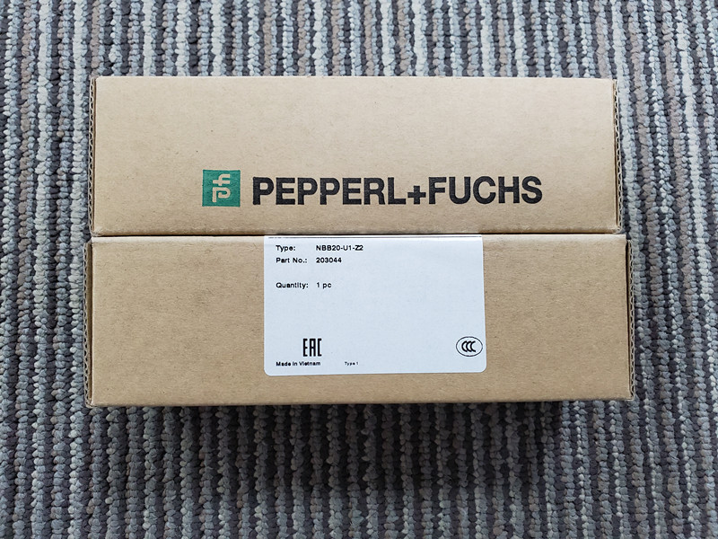
For quotation, provide NBB20-L3M-US-C3-V12, quantity, destination, required delivery date, target material, supply voltage, and a clear label photo. Mention whether a V12 cable, modular bracket, or mounting aid is required. Sunup-MTL can assist with model confirmation, quotation, packing, export documents, and global shipment. Final electrical compatibility, mounting clearance, machine safety, and commissioning remain the responsibility of qualified personnel.