From Field Contact to Control-System Decision: Applying Pepperl+Fuchs KCD2-SR-1.LB Correctly
Pepperl+Fuchs KCD2-SR-1.LB is a compact one-channel switch amplifier for transferring digital states from a NAMUR sensor or mechanical contact to the control side with galvanic isolation. The module provides a relay signal output, a second output that can be assigned as another signal or a fault indication, selectable line fault detection, and reversible operating logic. Its 12.5 mm housing is useful where cabinet space is limited, but the narrow format does not remove the need for careful sensor, contact, output-load, and failure-response checks.
Start With the Full Model Name, Not the Housing Color
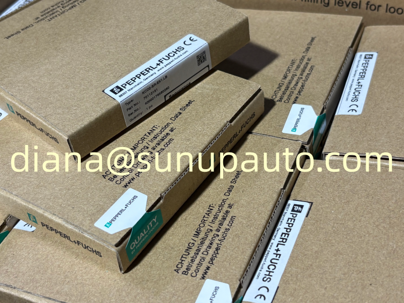
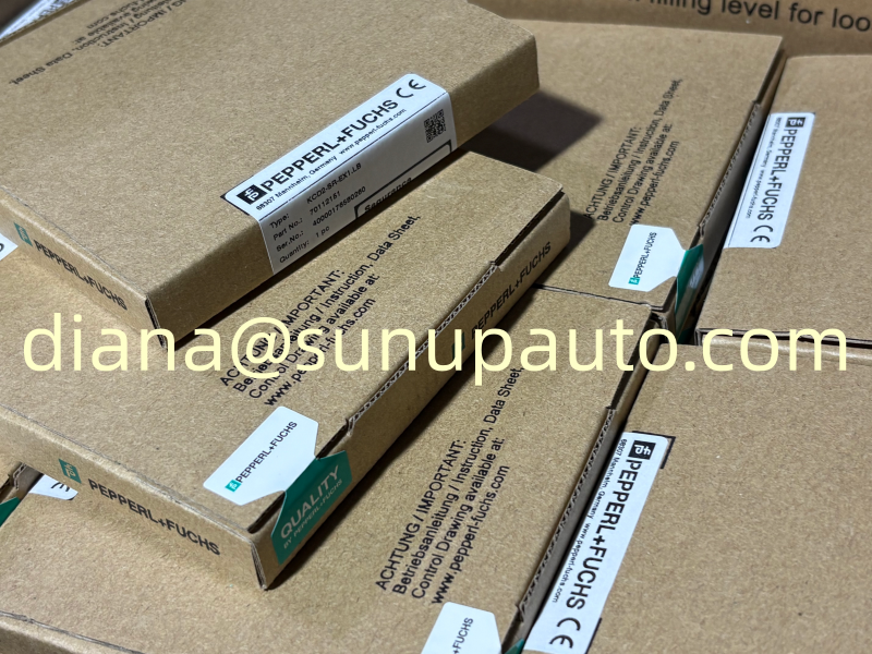
Pepperl+Fuchs offers several closely related KCD2 and KFD2 switch amplifiers. Some are ordinary signal conditioners, some are intrinsically safe barriers, and the suffixes define channel count, output style, diagnostics, terminal arrangement, and approvals. KCD2-SR-1.LB should therefore be ordered and documented by its full label. Do not substitute KCD2-SR-Ex1.LB, KFD2-SR2-Ex1.W.LB, or another visually similar module without an engineering comparison.
For replacement work, photograph the front and side labels, terminal numbers, switch positions, Power Rail arrangement, and conductor colors. Record whether the field circuit is a NAMUR proximity sensor or a dry contact. Also record what each relay output does in the control system. A second output used as a fault alarm requires a different acceptance test from a second output used to duplicate the process state.
How the Input State Becomes a Relay State
A NAMUR sensor communicates through current levels rather than a conventional high-voltage on/off signal. The switch amplifier supplies the sensor circuit and evaluates whether current is in the low or high state. Pepperl+Fuchs uses a nominal switching region between approximately 1.2 mA and 2.1 mA for this product family, with hysteresis to prevent relay chatter near the threshold. A mechanical contact can also be used when it is wired with the resistor network required for line fault supervision.
The control-system indication depends on both the physical input and the selected mode of operation. A closed contact can be configured to energize or de-energize the signal relay. Before setting the switches, define the process meaning of an active sensor, the normal operating state, the alarm state, and the desired response to loss of power. Write this logic in plain language and compare it with the cause-and-effect drawing.
Line Fault Detection Requires the Correct Field Circuit
The LB suffix indicates line fault monitoring. With a NAMUR sensor, the module can distinguish normal operating current from open- and short-circuit conditions. With a dry contact, resistor values must be installed so the amplifier can see valid current when the contact is open and closed. Without the correct resistor network, enabling line fault detection may create a permanent fault or fail to distinguish cable damage from a legitimate contact state.
Test line fault detection deliberately. Open one field conductor at an approved test point and confirm the fault indication, relay behavior, local LED, collective Power Rail message where used, and control-system alarm. Then create the approved short-circuit test and repeat the observations. Restore the circuit and confirm that the alarm clears without leaving an unintended bypass, force, or latched maintenance message.
Fault behavior should support maintenance rather than create ambiguity. Alarm text should identify the exact KCD2-SR-1.LB channel and distinguish wiring failure from the process state. If the second relay is configured as a fault output, document whether it energizes in the healthy condition or on fault. This detail affects how cable breaks and loss of module power are interpreted.
Three Configuration Decisions Control the Application
- Normal or reversed mode: choose the relationship between input current and the main relay state according to the process definition.
- Second output function: assign it as a duplicated signal output or a separate fault indication, then update drawings and control logic.
- Line fault detection: enable it only when the connected sensor or contact circuit supports the required supervision method.
Switch settings should be treated as controlled configuration. Record them in the loop sheet and check them after every replacement. A neighboring KCD2-SR-1.LB may have different settings because it serves a different fail-safe philosophy, even if the wiring appears identical.
Relay Outputs Need Real Load Information
The output contact may drive a digital input, annunciator, interposing relay, or another low-energy control load. Check voltage, current, inrush, contact type, minimum wetting current, and suppression for inductive loads. A relay contact can appear healthy on a meter but behave poorly with an extremely small PLC input current or a load that produces high inrush. Use the current Pepperl+Fuchs contact ratings and project derating rules for the actual environment.
Verify both electrical and logical operation. Measure the contact state at the KCD2-SR-1.LB terminals, confirm the receiving input changes, and check that the operator display shows the intended process condition. For shutdown or permissive service, test the complete path through the logic solver and final action under an approved procedure.
Power Rail, Heat, and Dense Cabinet Installation
KCD2-SR-1.LB can use a 24 V DC supply through the designated terminals or Power Rail. The Power Rail can simplify distribution and collective fault messaging, but feed-module capacity, redundancy, fuse protection, polarity, and total current must be checked. Do not feed the rail unintentionally through individual module terminals when the system instructions prohibit that arrangement.
The 12.5 mm housing supports high channel density. Inspect cabinet temperature near the center of the module group, not only at the enclosure door. Maintain terminal access and conductor separation, avoid excessive wire pressure on removable connectors, and provide labels that remain readable after adjacent channels are installed.
A Practical Acceptance Test
- Confirm model KCD2-SR-1.LB, supply method, terminal numbers, and all switch positions.
- Verify the sensor or contact type and the resistor network used for line monitoring.
- Simulate low and high input-current states and record the switching point behavior.
- Confirm main relay state, second relay function, local LEDs, and control-system indication.
- Test open- and short-circuit faults using the approved method and observe every alarm route.
- Remove power and confirm the designed de-energized response.
- Restore normal wiring, clear forces, and compare the final condition with the operating permit.
- Attach the test results, switch settings, and photographs to the maintenance record.
Troubleshooting by Symptom
Relay never changes: check module power, sensor current, terminal polarity, contact resistors, switch settings, and the physical target or actuator position.
Fault LED remains active: measure the field-loop resistance and current, inspect open conductors and shorts, then confirm line fault detection is appropriate for the connected circuit.
Local relay operates but the PLC does not: inspect output wiring, contact common and normally open terminals, receiving-channel power, input configuration, and interposing devices.
Intermittent switching: look for a sensor at the edge of its detection range, mechanical vibration, loose terminals, low load current, electrical noise, or input current hovering near the switching threshold.
Ordering Information for Maintenance and Projects
For quotation, provide KCD2-SR-1.LB exactly as written on the required label, quantity, destination, required delivery date, and a clear photograph of the installed module. Include the sensor type, output use, Power Rail arrangement, and switch settings when compatibility support is needed. Sunup-MTL can assist with product confirmation, quotation, packing, export documentation, and international delivery. Final selection, field wiring, fault behavior, functional-safety use, and commissioning must be verified by qualified personnel using current Pepperl+Fuchs documentation.