Expanding HART Monitoring Capacity with the Pepperl+Fuchs KFD0-HMS-16 Secondary Module
Pepperl+Fuchs KFD0-HMS-16 is a 16-channel HART multiplexer secondary module designed to expand a network built around the KFD2-HMM-16 primary module. It connects analog instrument loops to a centralized HART communication system so maintenance and asset-management software can obtain digital device information while the conventional process signal continues to serve the control system. KFD0-HMS-16 is especially relevant when a plant has many HART-capable transmitters but wants to add diagnostics and configuration access without replacing every analog input card.
The Secondary Module Has a Specific Role
KFD0-HMS-16 is not a stand-alone HART gateway. It receives its connection and operating support through the HART multiplexer architecture and must be used with the compatible KFD2-HMM-16 primary module. The secondary module does not require a separate external power supply; its supply connection is provided through the designated 14-channel flat cable from the primary module. A 26-pin flat cable carries the analog channel connections used for HART communication.
Each KFD0-HMS-16 adds sixteen HART channels. Pepperl+Fuchs permits up to fifteen secondary modules to be connected to one primary module, allowing a large population of field devices to be organized under one host connection. Maximum capacity should not be treated as the automatic design target. Polling performance, cabinet space, cable routing, documentation quality, maintenance ownership, and host-software limits all influence the practical network size.
Channel Mapping Is the Foundation of a Useful System
The multiplexer can communicate successfully while still showing the wrong plant tag if channel mapping is poor. Before installation, create a record that links every KFD0-HMS-16 channel to the control-system input, field tag, instrument model, cabinet terminal, loop drawing, and software address. Identify unused channels clearly and reserve expansion positions deliberately.
During commissioning, start with a known transmitter. Confirm its local tag and 4-20 mA value, then verify that the same device identity appears through the HART host. Continue through all sixteen channels. If several adjacent channels are missing, inspect the flat cable and connector alignment. If only one channel is unavailable, investigate the individual loop, terminating resistance, field-device HART capability, and channel assignment.
Communication Conditions Still Matter
KFD0-HMS-16 supports HART field-device inputs for revisions 5 through 7. Pepperl+Fuchs specifies an external terminating resistance of 230 to 500 ohms as standard, with values up to 1000 ohms possible under defined conditions. A loop that transmits an accurate analog current is not automatically a healthy HART communication path. Insufficient impedance, excessive electrical noise, poor grounding, unsuitable cable, or a device configuration problem can weaken the digital signal.
Keep analog and communication cables away from high-energy switching conductors. Maintain connector strain relief and avoid folding ribbon cables sharply. Check that screen and grounding practice follows the plant standard. When intermittent communication occurs, compare the affected channels with healthy channels on the same KFD0-HMS-16 before replacing hardware.
A Focused Commissioning Sequence
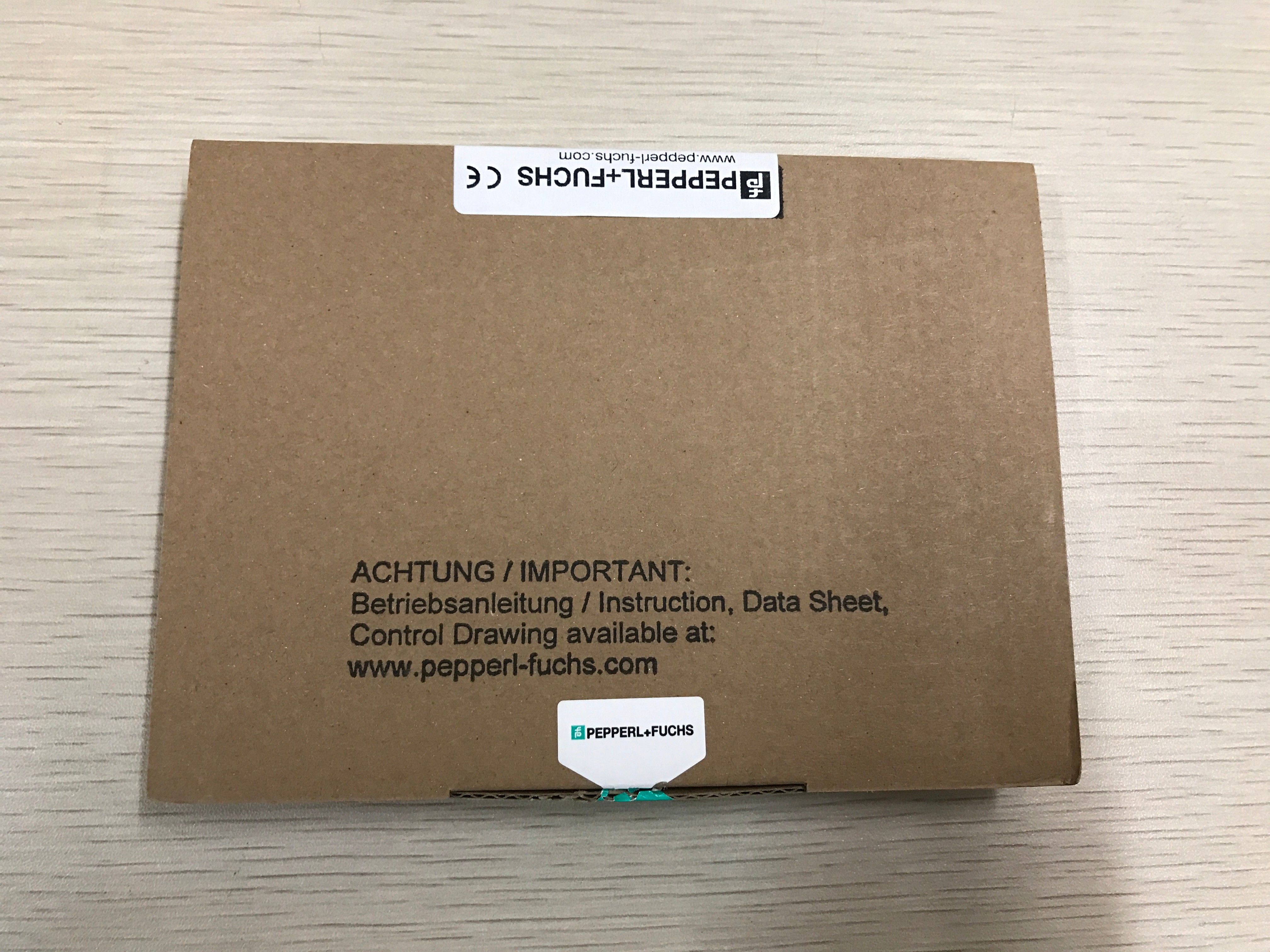
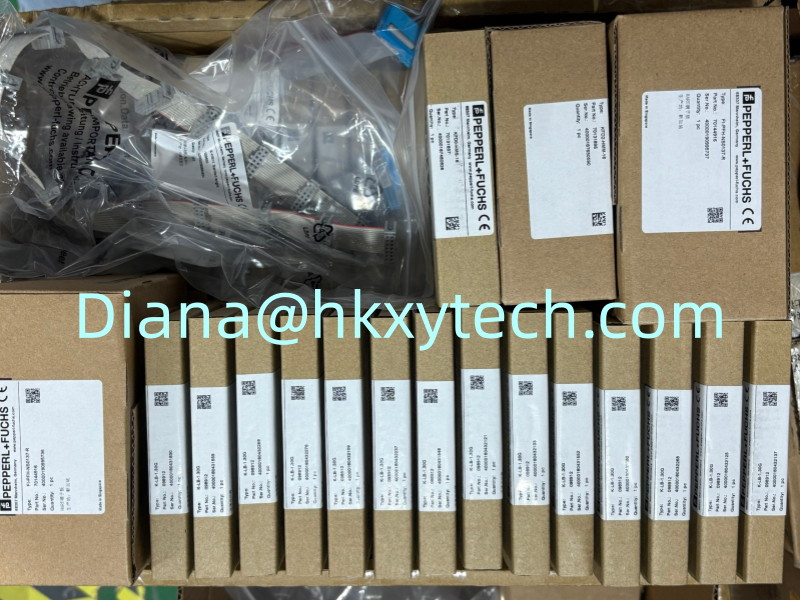
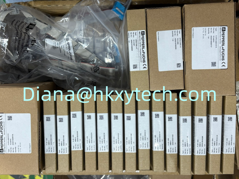
- Confirm that the received product label reads KFD0-HMS-16 and inspect all connectors for transport damage.
- Verify the compatible KFD2-HMM-16 primary module, expansion capacity, cable type, and intended secondary-module position.
- Label both ends of the 14-pin primary-to-secondary cable and the 26-pin analog connection cable.
- Compare the physical channel wiring with the approved loop and multiplexer schedules.
- Power the primary system and confirm the host recognizes the expected secondary channels.
- Interrogate each connected field device and compare its tag, range, units, and status with the engineering record.
- Record open channels, communication exceptions, and unsupported devices instead of leaving unexplained gaps.
- Save the final channel map and host configuration in the plant document system.
Maintenance Value Comes From the Workflow
A KFD0-HMS-16 network can expose device diagnostics, configuration data, manufacturer information, and instrument status, but someone must review and act on that information. Define who monitors alerts, how configuration changes are approved, and where completed work is recorded. Uncontrolled remote changes can create discrepancies between the field device and the approved instrument datasheet.
For safety-related use, Pepperl+Fuchs identifies the module with capability up to SIL 3 according to IEC/EN 61508. The statement applies within a complete assessed function and lifecycle. Host access, change control, proof testing, cybersecurity, field-device behavior, and control-system logic must remain consistent with the approved safety design.
Plan Capacity, Addressing, and Spare Strategy Together
A large multiplexer installation should be divided into recognizable cabinet or process groups instead of filling channels wherever space is available. Consistent numbering makes it easier to identify which KFD0-HMS-16 serves a unit, compare the host display with drawings, and isolate a communication problem without disturbing unrelated instruments. Leave documented spare channels where later plant modifications are likely, but do not connect unused field wiring without clear termination and labeling.
Keep one approved spare strategy for the complete HART network. A spare KFD0-HMS-16 should be stored with compatible ribbon cables, connector details, configuration records, and the latest channel schedule. Periodically inspect packaging and connector condition, especially in humid or dusty stores. When a spare is issued, replenish it using the full model number rather than a shortened family description.
Network documentation should also state the primary module, host interface, software version, device-management database, and communication route. This information becomes important after a computer upgrade or control-system migration, when the field hardware remains healthy but the host can no longer discover all channels. A controlled backup and a simple recovery test can protect more maintenance value than holding an undocumented spare module alone.
Replacement and Purchasing Information
Before removing an installed KFD0-HMS-16, photograph its label and cable positions, export the channel list, identify the associated primary module, and mark every connector. After replacement, verify all sixteen channels and any downstream secondary modules rather than checking only one responsive transmitter.
For quotation, provide KFD0-HMS-16, quantity, destination country, required delivery date, and a readable product-label photo. State whether KFD2-HMM-16, K-HM14 connection cables, analog ribbon cables, Power Rail accessories, or software support are also required. Sunup-MTL can assist with model confirmation, packing, export documentation, and international shipment. Final compatibility and configuration should be checked against current Pepperl+Fuchs documents and the plant's approved maintenance standard.