Preserving RTD Resistance Accuracy Across the Hazardous-Area Boundary with KCD2-RR-EX1
Pepperl+Fuchs KCD2-RR-EX1 is a one-channel isolated resistance repeater used to transfer resistance values from hazardous-area RTDs or potentiometers to safe-area control equipment. It supports Pt100, Pt500, and Pt1000 inputs together with resistance transmission, allowing the receiving input card to measure a load comparable to the field resistance. The module is useful where the control system already performs temperature linearization and the project wants intrinsic-safety separation without converting the signal into a different process-current format.
The Receiving Card Still Interprets the Temperature
KCD2-RR-EX1 repeats resistance; it does not remove the need to select the correct RTD characteristic in the control system. A Pt100, Pt500, and Pt1000 can all indicate the same temperature while presenting different resistance values. The receiving input must be configured for the actual field element and the applicable IEC, DIN, or project curve.
Before commissioning, verify sensor type, nominal resistance, alpha value where applicable, measuring range, wiring method, and the expected resistance at a known temperature. If a replacement module is installed in a loop that already reads incorrectly, check the control-system configuration before recalibrating the field sensor.
Two, Three, or Four Wires Change the Error Budget
KCD2-RR-EX1 supports two-, three-, and four-wire techniques. A two-wire circuit includes both lead resistances in the measurement and is most sensitive to cable length and temperature. A three-wire circuit compensates lead resistance when the conductors are well matched. A four-wire circuit provides the strongest compensation because current and voltage paths are separated.
Do not select the wiring mode only from conductor count at the cabinet. Trace the cable to the sensor head and check junction boxes, terminal links, and spare cores. A three-wire RTD with two conductors accidentally joined at an intermediate terminal can behave like a two-wire sensor and introduce a stable but significant temperature offset.
Accuracy Depends on the Whole Resistance Path
Pepperl+Fuchs publishes an accuracy reference of 0.1 percent for KCD2-RR-EX1. The installed loop uncertainty also includes sensor tolerance, sensor drift, lead mismatch, terminals, calibration equipment, receiving-card accuracy, temperature effects, and control-system scaling. A narrow process limit may require an uncertainty calculation rather than a simple comparison with one module specification.
For Pt100 applications, line fault detection can help identify open or abnormal wiring. The diagnostic should be tested using the actual connection method and receiving input. A fault indication must lead operators to the correct loop without being mistaken for a real high or low process temperature.
Bench and Field Checks That Reveal Different Problems
- Zero-resistance and continuity checks: identify open conductors, loose terminals, and unexpected links before energizing.
- Known-resistance simulation: apply several calibrated resistance values and compare the safe-area reading with the expected temperature.
- Ambient comparison: compare the field sensor with a trusted reference at a stable temperature to expose sensor or installation error.
- Lead-balance check: measure individual conductors in a three-wire circuit and investigate material mismatch or damaged cable.
- Fault test: create an approved open-circuit condition and confirm the diagnostic and control-system response.
Document both resistance and displayed temperature. If the resistance transfer is correct but the displayed value is wrong, focus on the receiving card, sensor curve, range, or engineering-unit configuration rather than replacing KCD2-RR-EX1 again.
Power Rail and Cabinet Integration
The module uses a 24 V DC supply and can receive power through the Pepperl+Fuchs Power Rail or the designated terminals. Its narrow 12.5 mm housing supports dense cabinet layouts. Confirm Power Rail polarity, feed-module capacity, grouping, ventilation, and fault monitoring before adding modules to an existing rail.
Maintain separation between intrinsically safe and non-intrinsically safe wiring, use the correct blue and green terminals, and preserve labeling. Check hazardous-area entity parameters, cable capacitance and inductance, gas or dust group, temperature class, and certificates for the complete loop. The KCD2-RR-EX1 model designation does not replace the project-specific intrinsic-safety calculation.
Use the Error Pattern to Locate the Fault
A constant temperature offset across the operating range often points to lead resistance, an incorrect wiring mode, or a receiving-card offset. An error that grows with temperature can indicate the wrong RTD curve, sensor type, or scaling. Sudden jumps are more consistent with loose terminals, moisture, cable damage, or an intermittent sensor. A reading fixed at an extreme value should trigger open- or short-circuit checks before calibration is attempted.
Compare the resistance at the field sensor, at the cabinet terminals, and at the KCD2-RR-EX1 input during a stable process condition. This staged measurement shows where resistance changes enter the loop. Use equipment and procedures suitable for the hazardous-area classification, and do not disconnect an energized intrinsically safe circuit unless the site method permits it.
If several channels in one cabinet drift together, investigate ambient temperature, Power Rail voltage, shared terminations, and the receiving input assembly. Replacing individual modules may hide a common cause. Conversely, if one channel fails while neighboring channels remain stable, compare its sensor, cable route, terminal tension, and switch configuration with a healthy reference channel.
Records That Make Future Calibration Faster
The loop file should retain sensor type, wiring method, range, calibration resistance points, measured values, test-equipment identity, switch settings, and final control-system indication. Include a photograph showing terminal numbers and conductor colors. When this information accompanies the KCD2-RR-EX1 history, the next technician can reproduce the test instead of rebuilding the circuit description from memory.
Procurement and Replacement Notes
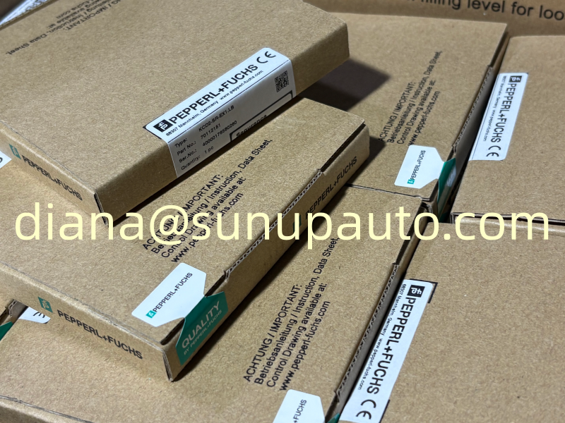
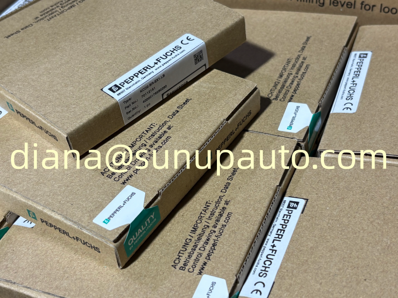
For replacement, photograph the existing KCD2-RR-EX1 label, record switch positions, wiring mode, sensor type, and terminal arrangement, then isolate the circuit according to plant procedure. After installation, simulate more than one resistance point and test line fault behavior where used.
For quotation, provide KCD2-RR-EX1, quantity, destination, required delivery date, and whether Power Rail accessories, terminals, or related barriers are needed. Sunup-MTL can support model confirmation, packing, export documentation, and international shipment. Final sensor compatibility, accuracy assessment, intrinsic-safety approval, installation, and calibration should be completed by qualified personnel using current Pepperl+Fuchs information.