Checking Load Voltage, Loop Control, and Safe Operation with the Eaton MTL5521 Solenoid Driver
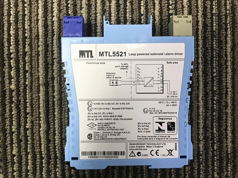
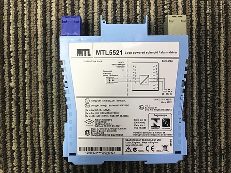
Eaton MTL5521 is a one-channel loop-powered solenoid and alarm driver that enables a safe-area control signal to operate a certified low-power intrinsically safe load in a hazardous area. Typical loads can include solenoid valves, alarms, LEDs, and other suitable low-energy devices. The module is frequently selected for process shutdown valves, pneumatic actuators, warning indicators, and package-unit control where the available output voltage and current must be matched carefully to the real field load and cable.
The Load Calculation Comes Before the Order
A solenoid that operates from a laboratory power supply may fail at the end of a long hazardous-area cable. MTL5521 has a published minimum output reference of 13.6 V at 48 mA, with a 48 mA minimum current limit and a maximum output reference of 24 V from a 180-ohm equivalent circuit. The actual field voltage is reduced by cable resistance, terminals, protection devices, and the load current.
Calculate the loop at minimum supply voltage, maximum conductor resistance, highest expected current, and worst operating temperature. Compare the remaining voltage with the solenoid or alarm manufacturer's minimum pickup requirement. For a valve, also confirm pneumatic pressure, spring return, mechanical friction, and the required energized or de-energized state; an electrical calculation cannot prove the final element will move correctly.
Control Philosophy Defines the Safe Test
Before forcing MTL5521 on or off, determine what the connected equipment will do. Energizing a solenoid may open a process valve, release pressure, start dosing, or change a shutdown state. Coordinate testing with operations, apply permits and bypass controls, and isolate the process consequence where possible. Use a simulator or disconnected test load when operating the real final element would be unsafe.
The yellow LED indicates that the output is active, but it does not confirm that current reaches the field load or that the valve has moved. Verify the control command, module indication, field voltage, loop current, solenoid condition, and independent position feedback as separate observations.
Electrical Performance and Cabinet Loading
MTL5521 uses a 20 to 35 V DC supply. Eaton lists maximum current consumption of 90 mA at 24 V and internal power dissipation of about 1.4 W at 24 V. Output ripple is below 0.5 percent of maximum output, peak to peak, and the output should reach within 10 percent of its final value within 100 ms. The operating-temperature reference extends from -20 to +65 degrees C.
When several drivers are installed together, calculate total DC supply demand and enclosure heat. Check rail spacing, airflow, terminal access, and the temperature near the center of the module group. A cabinet can have sufficient power capacity while still operating too hot for long-term reliability.
Commissioning From Command to Final Element
- Verify the MTL5521 label, terminal numbers, supply polarity, and hazardous-area segregation.
- Confirm that the field load is approved for the selected intrinsic-safety loop and that entity parameters are compatible.
- Measure the module supply with the output inactive and active.
- Apply a controlled safe-area command and confirm the yellow status indication.
- Measure output current and voltage at the module, then repeat at the field load to identify cable drop.
- Observe the physical valve, alarm, or indicator and confirm any independent feedback.
- Test loss of command and loss of power to verify the designed fail position.
- Remove all forces and bypasses, return control to normal, and record the as-left state.
Troubleshooting by Measurement
LED on, load inactive: measure voltage at the field device, inspect cable continuity and polarity, and compare the load resistance with its datasheet. A stuck valve or missing instrument air can look like an electrical failure.
Output collapses when energized: look for a short circuit, excessive load current, low DC supply, high cable resistance, or an incompatible solenoid. Verify the loop with a suitable test load before replacing the module.
Slow or intermittent operation: check terminal tightness, voltage margin, coil temperature, mechanical friction, pneumatic pressure, and control pulse duration. A short control pulse may end before the final element completes its stroke.
Separate Electrical Acceptance From Process Acceptance
Electrical acceptance proves that MTL5521 receives the command and delivers the expected voltage and current to a representative load. Process acceptance proves that the connected valve, alarm, or indicator performs its required duty under operating conditions. Both records are needed. A correct electrical output cannot compensate for a seized valve, incorrect actuator spring, restricted air supply, or misadjusted position switch.
For a shutdown valve, record command time, coil energization, start of movement, full travel, and feedback arrival. Compare those times with the safety or operating requirement. For an alarm or LED, confirm visibility or audibility at the intended location and verify that loss of power produces the expected state. Where operations cannot permit a live process test, document the limitation and schedule the remaining test for an approved opportunity.
Trend supply voltage and cabinet temperature if repeated failures occur. Several MTL5521 channels operating near maximum load can expose a weak DC supply or thermal problem that is not visible during a single-channel bench test. Correcting the shared cause can prevent repeated module replacement and unplanned downtime.
Keep one completed loop calculation with the maintenance record, including cable length, conductor size, measured resistance, field-load data, and minimum tested supply voltage. This gives future buyers and technicians a clear basis for confirming another MTL5521 or evaluating a replacement without repeating the original investigation.
Ordering and Documentation
For an MTL5521 inquiry, provide the exact model, quantity, destination, delivery deadline, load type, operating current, cable length, and a clear label photo. Distinguish MTL5521 from suffix variants such as MTL5521-T and from other MTL5500 solenoid drivers with different output capability or fault functions.
Sunup-MTL can assist with product confirmation, quotation, packing, export documents, and international delivery. Final load compatibility, intrinsic-safety calculations, control philosophy, installation, testing, and plant acceptance must be completed by qualified personnel using current Eaton documentation and approved loop drawings.