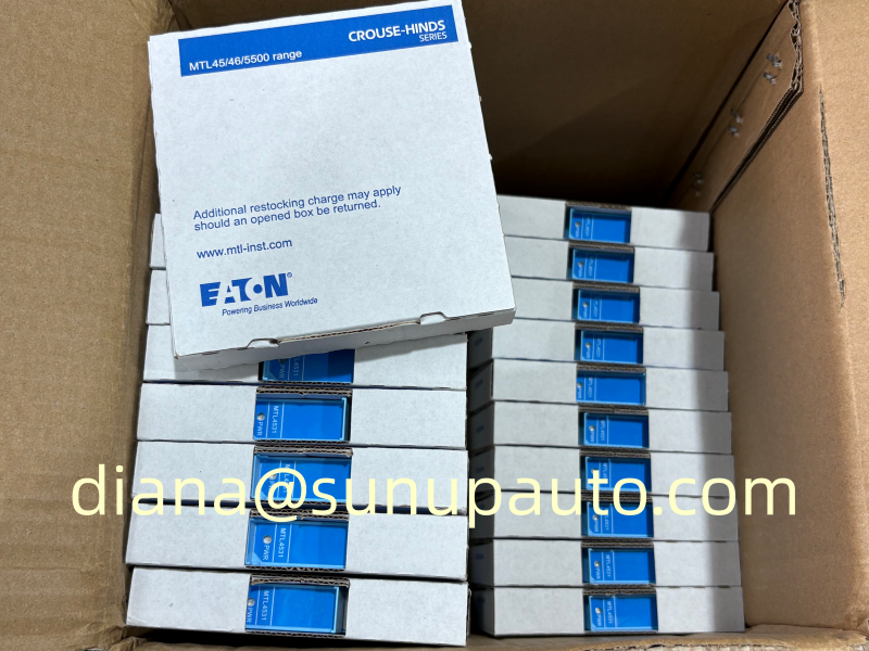
Eaton MTL RTK P725C Annunciator Components for Existing Process Alarm Panels
The MTL RTK P725C designation is associated with the Eaton RTK 725 alarm annunciator platform, a modular system used to present clear visual alarm information in control rooms and local process panels. The 725 family can be arranged from a single alarm channel to large systems with as many as 256 channels, making configuration identification essential when a replacement component is required.
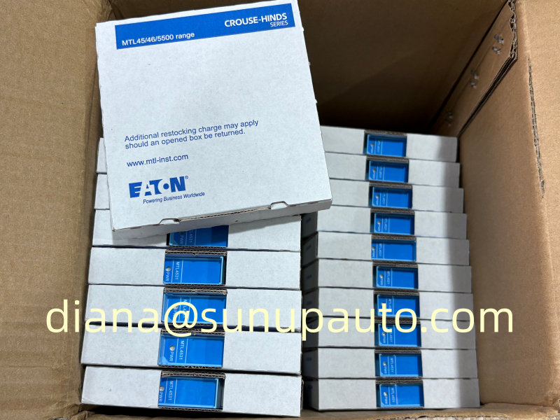
Designed for Alarm Visibility and System Resilience
The RTK 725 platform uses a modular, multi-redundant architecture intended to avoid a single point of failure. Projects may specify different window sizes, six window colours, lamp or LED illumination depending on the version, and selectable alarm sequences. Each alarm way can be configured from the front of the system, while an optional bidirectional RS485 communication facility supports integration with supervisory equipment.
Mechanical arrangements include panel mounting, 19-inch rack assemblies, and wall- or floor-mounted enclosures. Published family information identifies 24 VDC logic and field-contact supplies for 725B/725C systems. Operating references extend from -20 to +60 degrees C, with non-condensing humidity up to 95 percent; enclosure protection depends on the selected assembly and installation.
Replacement Scenario
A control-room technician finds one alarm card or display position no longer responding during a planned test. The purchasing request says only “P725C,” but the panel includes uniquely addressed cards and a site-specific software configuration. Before a spare is ordered, the team records the full part code, card address, window arrangement, power details, installed options, and current configuration file. That short inspection prevents a mechanically similar but incompatible component from reaching site.
When cards are replaced, the original configuration may need to be downloaded to the new hardware. This work should be planned with the responsible control and safety personnel so alarm sequences, acknowledgement behavior, lamp tests, communications, and event indications can be verified before the panel returns to service.
Details Required for a Useful Quotation
- Complete RTK P725C label and part number, not only the family name.
- Card type, address, channel count, window format, and illumination type.
- System voltage, communications option, and enclosure or mounting style.
- Quantity, condition requirement, destination, and delivery deadline.
- Required manuals, traceability, test documents, or export paperwork.
Sunup-MTL can assist with model checking and sourcing for MTL RTK P725C maintenance demand. Final compatibility, configuration loading, testing, and commissioning remain subject to the approved project documents and qualified site engineering review.
Alarm Annunciation Is Part of the Operator Response
An annunciator is not simply a group of lamps. It presents abnormal conditions in a sequence that helps an operator detect, understand, acknowledge, and respond to an event. An RTK P725C panel may be configured to distinguish a new alarm, a returned-to-normal condition, an acknowledged alarm, and a standing fault through different flashing and audible behaviors. The selected sequence must match the plant alarm philosophy and the way operators are trained to work.
When a spare component is installed, the visible indication may appear correct while acknowledgement logic, horn behavior, repeat alarm, reset, or communication functions remain incorrect. Testing must therefore cover the complete cause-and-effect sequence, not only lamp illumination.
Capture the Configuration Before Maintenance
Before replacing an RTK P725C card or assembly, record the full model and revision, physical position, card address, channel assignments, alarm sequence, input contact logic, window color, legend text, horn grouping, and communication settings. Save the approved software configuration and confirm that it can be restored. Photographs of the front windows and rear connections provide a useful cross-check, but they should not replace the controlled configuration file and wiring drawings.
If the original card is still partly operational, compare its settings with the project documents before removal. Old panels may contain authorized field changes that never reached an early drawing revision. Any discrepancy should be resolved through the site's change-management process rather than copied without review.
Recommended Functional Test Sequence
- Verify power supply voltage, polarity, fusing, and cabinet earth before energizing the replacement.
- Confirm card address, channel allocation, and downloaded configuration.
- Operate the lamp or LED test and inspect every window for brightness, color, and correct legend.
- Simulate each selected input and verify first-out, flashing, horn, acknowledge, reset, and return-to-normal behavior.
- Check common relays, audible devices, remote contacts, and RS485 communications where fitted.
- Confirm that a single card fault does not create misleading indications elsewhere in the panel.
- Record test results, outstanding defects, software version, and the person authorizing return to service.
Testing should be planned so that simulated alarms cannot trigger an unintended plant trip or create confusion in the control room. Coordinate with operations, bypass affected external actions only through an approved procedure, and restore all bypasses after the test.
Window Layout and Human Factors
The 725 family supports different window sizes and colors, so a replacement panel component must fit the existing visual scheme. Legends should use clear wording, consistent equipment tags, and readable text size. Color should support the site standard rather than act as the only way to distinguish priority. Frequently occurring nuisance alarms should be corrected at their source instead of being accepted as normal annunciator activity.
Where several alarm cards form one large panel, keep the physical window schedule synchronized with the logic schedule. A mismatched legend can send an operator to the wrong equipment even when the electronics function correctly. Receiving inspection should therefore compare both the electrical part number and any supplied window or legend components.
Maintenance Records and Spare Strategy
A useful RTK P725C spare plan identifies installed quantities, card types, display options, communication modules, power components, and unique project configurations. Store configuration backups in a controlled location and verify periodically that the programming tools remain available. Spares should be protected from moisture, dust, electrostatic discharge, and mechanical damage.
For quotation, provide the complete RTK P725C code, photographs, card address, panel arrangement, required quantity, destination, delivery date, and document requirements. State whether the request concerns a complete annunciator, a card, a display assembly, or another system component. Sunup-MTL can assist with sourcing and commercial coordination, while qualified site personnel must approve configuration, installation, testing, and return to service.