Design Note for Eaton MTL4544S Dual-Channel HART Repeater Power and Current-Sink Output Loops
Eaton MTL4544S is a dual-channel MTL4500 repeater power supply for two-wire or three-wire 4-20 mA and HART transmitters in hazardous areas. Each channel supplies the field transmitter and repeats its measurement to a safe-area current-sink output. The module is intended for backplane-mounted systems where two analogue loops must be handled in one position and the receiving side provides the voltage source required by the current-sink output arrangement. Correct application depends on distinguishing the S variant from the standard source-output MTL4544.
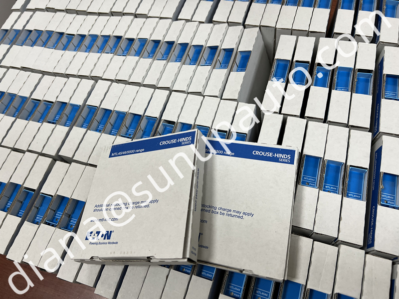
Two Channels Save Space but Increase the Need for Clear Records
MTL4544S contains two independent measurement channels. The dual-channel arrangement reduces backplane positions and cabinet width, but one module replacement affects two process loops. Both loop tags, transmitter models, ranges, safe-area destinations, and bypass requirements must be identified before work begins. Do not assume channel 1 and channel 2 serve the same unit or have the same shutdown consequence.
Label the module with both loop references and keep the channel assignment consistent across the backplane drawing, system cable schedule, termination panel, controller database, and maintenance record. During an outage, verify each channel separately. A correct signal on channel 1 does not prove channel 2 wiring, HART path, or scaling is correct.
The S Suffix Changes the Safe-Area Electrical Relationship
The standard MTL4544 drives current into safe-area loads. MTL4544S instead acts as a current sink. The connected control-system input or external circuit must provide a compatible voltage source. Eaton lists a maximum current-sink load of 600 ohms and a maximum voltage source of 24 V DC for the related MTLx544S arrangement. Verify the actual input card, terminal assembly, polarity, and source voltage before connection.
An active analogue input connected to a source-output isolator can create competing supplies. A passive input connected to MTL4544S may provide no loop energy. These errors can look like failed hardware even though the module is healthy. Trace each safe-area circuit and measure its open-circuit voltage using an approved method before selecting the S variant.
Field-Side Power and Current Transfer
Each channel provides a floating DC supply for a conventional two-wire or three-wire transmitter and repeats a 4-20 mA signal. Eaton gives an input signal range extending to 24 mA including over-range and a transmitter-voltage reference of 16.5 V at 20 mA. Cable resistance and transmitter requirements must be checked at the highest expected current and lowest backplane supply.
For separately powered four-wire current sources, the MTLx544 family can accept the current under the documented connection method, but HART communication is not supported in that arrangement. If the application uses a four-wire analyzer or flow computer, confirm both the current path and the communication requirement before approving MTL4544S.
The module operates from a 20 to 35 V DC supply through the MTL4500 backplane. Eaton lists maximum current consumption around 96 mA at 24 V with two 20 mA signals and higher internal dissipation for the current-sink S variant than for the standard model. Include both channels in power and thermal calculations.
HART Communication Has a Channel-Specific Path
MTL4544S supports bidirectional HART communication for suitable smart two-wire transmitters. Communication is associated with the designated field terminals for each channel. Test the channels separately and confirm that the host device tag matches the physical loop. Crossed channel documentation can allow communication with the wrong transmitter while the technician believes the intended loop has been verified.
If analogue current is correct but HART is unavailable, check transmitter type, loop impedance, modem connection, terminal selection, shielding, grounding, electrical noise, and whether the source is a separately powered four-wire device. Read-only communication testing should capture device identity, range, units, status, and diagnostics without changing approved parameters.
Backplane Selection Is Part of the Product Choice
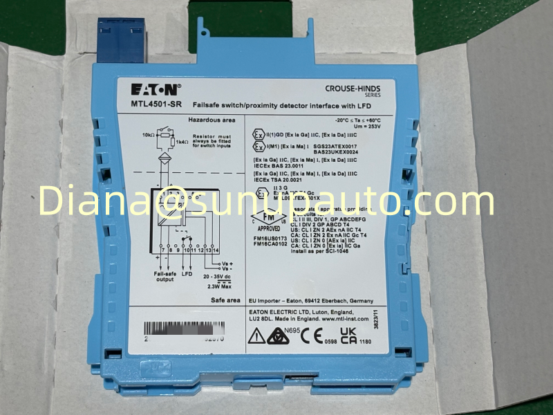
MTL4544S is a backplane-mounted MTL4500 module. The backplane defines safe-area routing, power distribution, system cabling, and slot keying. Confirm the backplane part number and slot assignment before purchasing a replacement. Inspect the base connector for bent contacts, contamination, looseness, and heat damage. Replacing the plug-in module will not correct a damaged backplane or system cable.
Compare the wiring with the current MTL4544S terminal diagram because MTL4500 and MTL5500 safe-area terminal arrangements differ. If a project migrates from backplane-mounted MTL4500 hardware to DIN-rail MTL5500 hardware, plan new terminations, power distribution, mounting, testing, and documentation rather than treating the two modules as mechanically interchangeable.
Optional One-Input, Two-Output Use Needs Special Review
Eaton documents an arrangement in which the two input channels can be interconnected so one two-wire transmitter drives two safe-area loads. This can provide two isolated receiving paths, but it changes the normal channel architecture. HART communication is transferred through channel 1 output only in the documented arrangement. Use this mode only with the correct manufacturer diagram and a project-specific review.
Identify which load is primary, how each system handles under-range and over-range, and whether failure of one receiving path can affect the other. Test both outputs at several current values and confirm that maintenance on one destination will not unintentionally interrupt the second destination.
Commissioning Plan for Both Channels
- Verify MTL4544S, backplane model, slot, supply voltage, connector condition, and both loop tags.
- Confirm each transmitter is two-wire, three-wire, or an approved separately powered current source.
- Verify each safe-area destination provides the voltage required by the current-sink output.
- Check polarity and measure open-circuit voltage before connecting the outputs.
- Test channel 1 at low, middle, high, under-range, and over-range current values.
- Repeat the complete test for channel 2 and compare control-system engineering units.
- Verify HART device identity and diagnostics independently on both eligible field loops.
- Test alarms, shutdown functions, or voting logic affected by each signal.
- Remove forces and bypasses, restore shields and covers, and save the as-left results.
Interpreting Faults Without Swapping Parts at Random
Both channels fail together: check backplane supply, slot connector, system cable, shared termination, and receiving-system power before replacing MTL4544S.
Only one channel fails: compare transmitter power, loop current, field cable, safe-area source voltage, and channel wiring with the healthy channel.
Output current is low on an S variant: verify that the receiving circuit provides enough voltage and that total load resistance is within the current-sink limit.
Current is accurate but HART is missing: confirm the correct terminals, transmitter wiring type, loop impedance, and whether a one-input/two-output connection limits the communication path.
Safety Lifecycle and Purchase Details
Eaton documents the MTL4544S family for functional-safety applications, subject to the approved architecture, safety manual, proof testing, failure response, and management of change. The complete loop includes the transmitter, barrier, backplane, receiving system, wiring, diagnostics, and process action. Intrinsic-safety parameters and certificates must also be reviewed for each connected field loop.
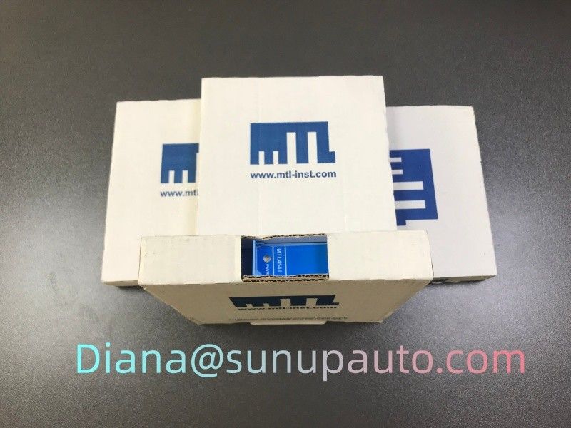
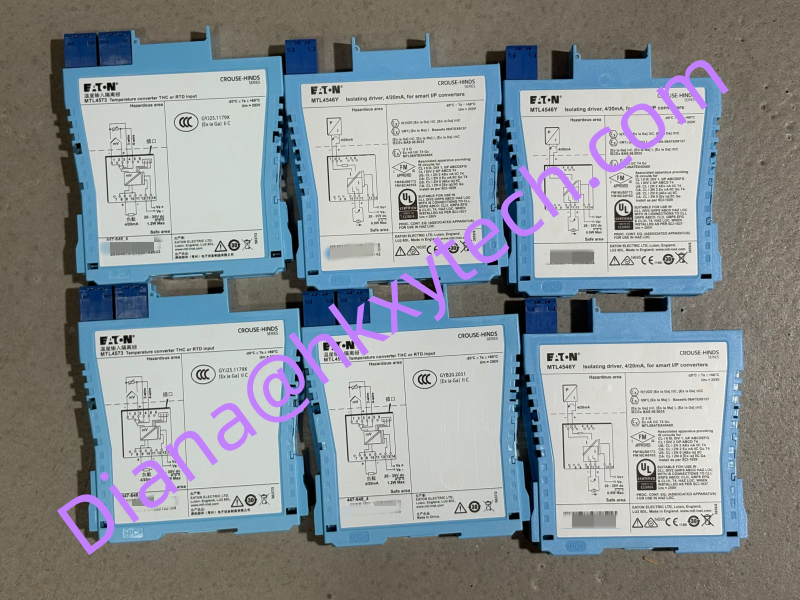
For an MTL4544S inquiry, provide the exact suffix, quantity, destination, delivery deadline, backplane model, transmitter types, and safe-area input details. Include label and backplane photographs when replacement compatibility needs confirmation. Sunup-MTL can assist with quotation, product checking, protective packing, export documents, and global delivery. Final design, current-sink compatibility, HART performance, installation, and acceptance testing should be completed by qualified personnel using current Eaton documentation.