Applying Eaton MTL4501-SR in Fail-Safe Switch and Proximity Detector Shutdown Loops
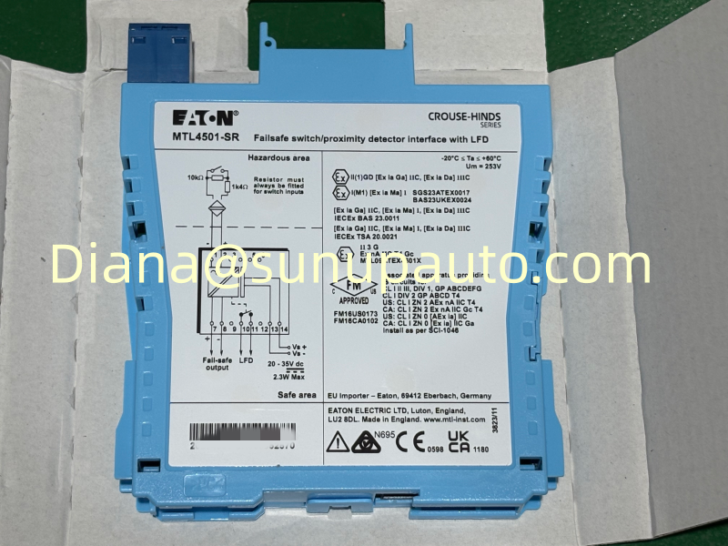
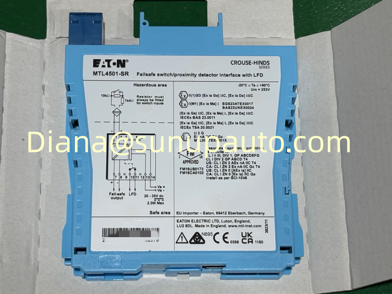
Eaton MTL4501-SR is a single-channel intrinsic-safety isolator that connects a hazardous-area switch or NAMUR proximity detector to a safe-area voltage input. It is designed for MTL4500 backplane mounting and for fail-safe applications where an off state, wiring fault, internal fault, or loss of power must drive the output toward the defined safe condition. MTL4501-SR is often requested for safety instrumented systems, trip circuits, valve-position confirmation, machine-state detection, and plant replacement work where the exact installed model and backplane arrangement must be maintained.
Start With the Required Safe State
The most important design question is not whether the field contact is normally open or normally closed. It is what the process must do when the hazardous-area sensor reports a demand, the field cable opens, the cable shorts, the barrier fails, or the module loses power. MTL4501-SR provides a fail-safe voltage output whose behavior is intended to support de-energize-to-trip architectures. The complete cause-and-effect design must define which electrical state represents normal operation and which state initiates the safe action.
Eaton documentation describes the output switching on at a nominal 24 V when the sensor input current is in the normal on range. Field wiring faults and internal faults drive the output off. That response is useful only when the receiving safety logic is configured to interpret it correctly. Confirm the input type and diagnostic behavior of the connected safety PLC, trip amplifier, or other safe-area equipment before commissioning.
Sensor and Switch Inputs Are Not Wired the Same Way
A compatible NAMUR proximity detector naturally presents defined current states that MTL4501-SR can monitor. A dry switch contact needs a resistor network so the module can distinguish an open contact from an open cable and a closed contact from a short circuit. Eaton's safety documentation shows a 1.4 kΩ series resistor and a 10 kΩ shunt resistor for switch-input fault monitoring. These resistors must be installed in the approved field arrangement, not improvised at the cabinet without reviewing the loop drawing.
During replacement, inspect the sensor type and resistor locations before assuming the old wiring is correct. Maintenance changes made over many years can leave a loop that still changes state but no longer detects faults as intended. Measure the loop current in normal, demand, open-circuit, and short-circuit conditions with an approved test method, then compare the results with the current MTL4501-SR documentation.
Line Fault Detection Is Diagnostic, Not the Safety Function
MTL4501-SR includes line fault detection, commonly abbreviated LFD. The LFD alarm helps maintenance teams identify open or shorted field wiring, but Eaton states that this function is not safety-related. The safety design should not claim extra integrity simply because a separate fault alarm is available. Instead, use the alarm to improve diagnostic coverage, response time, and maintenance clarity while keeping the safety action based on the approved fail-safe signal path.
Route and label the LFD indication so operators can distinguish a process demand from an instrument fault. A shutdown caused by a real sensor demand, an open cable, and a failed power supply may all produce a de-energized safety output, but they require different maintenance actions. Alarm text, cabinet drawings, and operating procedures should make those distinctions visible.
A Proof Test Should Challenge More Than the Sensor
- Confirm the complete model number MTL4501-SR, product build revision, backplane position, and terminal assignment.
- Verify the 20 to 35 V DC backplane supply under normal load and identify how loss of supply is alarmed.
- Operate or simulate the hazardous-area sensor and confirm that the safe-area voltage output changes as designed.
- Create a controlled open circuit and confirm the output moves to the safe state while the expected line-fault indication appears.
- Create a controlled short circuit using the approved procedure and confirm both safety output and diagnostic response.
- Verify the receiving safety-system channel, trip logic, final element, and operator indication through the full cause-and-effect path.
- Restore every bypass, force, link, and field connection, then independently confirm the as-left operating state.
Proof-test scope and interval must come from the safety requirements specification and the verified failure-rate calculation. MTL4501-SR can be used in safety functions up to SIL 3 when the complete architecture, diagnostics, proof testing, and lifecycle controls satisfy the applicable requirements. A product certificate does not by itself establish the achieved SIL of the instrumented function.
Backplane Compatibility and Controlled Replacement
MTL4501-SR is the backplane-mounted member of the safety-related pair; the functionally related MTL5501-SR uses DIN-rail mounting and different safe-area connections. They should not be exchanged only because their model numbers and functions look similar. Verify the MTL4500 backplane, safe-area connector, system cable, power distribution, and cabinet documentation before ordering or installing a spare.
Before removal, record the product build revision, photograph the label and connector positions, confirm the field loop is isolated, and identify active bypasses. Inspect the replacement for shipping damage and bent contacts. After installation, carry out a functional test of the normal input, demand state, open circuit, short circuit, LFD alarm, receiving logic, and final element. Update the maintenance record with the serial number and test result.
Procurement Information for MTL4501-SR
A useful request should include MTL4501-SR exactly as shown on the label, quantity, product build revision when relevant, destination country, required delivery date, and a description of whether the module is for an urgent trip-loop repair, planned shutdown, or long-term safety spare. Include a label photograph and backplane reference when the installed documentation is uncertain.
Sunup-MTL can assist with stock communication, quotation, export packing, documentation, and international delivery for MTL4501-SR and related MTL4500 components. Selection, intrinsic-safety calculations, functional-safety verification, proof-test design, installation, and final acceptance remain the responsibility of qualified engineering and safety personnel working from current manufacturer information and approved project records.