Engineering a Stable Passive-Input 4-20 mA and HART Signal Path with Eaton MTL4541A
Eaton MTL4541A is a single-channel current repeater designed for a separately powered 4-20 mA transmitter located in a hazardous area. The passive input accepts the transmitter current, transfers the measurement to a safe-area load, and preserves bidirectional HART communication on the analogue loop. This makes MTL4541A useful in backplane-based MTL4500 systems where an existing four-wire transmitter, analyzer, flow computer, or externally powered instrument must be connected to a control-system analogue input without losing isolation or digital maintenance access.
Why the A Variant Matters in a Measurement Loop
The letter A identifies an important electrical arrangement. MTL4541A is intended for a passive input from a separately powered transmitter. It does not provide the field transmitter supply used by a standard two-wire repeater power supply. The field device must obtain power from its own approved source and then drive current through the MTL4541A input. Selecting the wrong variant can produce an open loop, conflicting power sources, poor HART performance, or a signal that cannot reach its full operating range.
Before replacing an installed module, trace the loop from the field device to the backplane and control-system input. Confirm where the transmitter receives power, whether the signal is sourcing or sinking current, and which conductor carries the return path. A drawing that simply says “4-20 mA input” is not enough. Record the transmitter model, power supply voltage, barrier terminal assignment, receiving-card type, and loop polarity before disconnecting MTL4541A.
Check the Complete Voltage and Resistance Budget
Eaton specifies a 4-20 mA signal range with under-range and over-range capability from 1.0 to 21.5 mA. The MTL4541A input introduces a voltage drop that must be included in the field loop calculation. At 20 mA, the published maximum input voltage drop is below 6.6 V, equivalent to a transmitter load of about 330 ohms. The external transmitter power supply must also cover cable resistance, protection devices, terminals, and any other series load while maintaining the transmitter's minimum operating voltage.
Do the calculation at maximum expected current and minimum available supply voltage. Include the resistance of both cable conductors at the highest expected temperature. If the loop reaches 20 mA during a workshop test but clips during plant operation, measure the voltage at the transmitter and at the MTL4541A input under the real load. A marginal voltage budget often appears only at high process values or when long cables become warm.
Safe-Area Output and Receiving-Card Compatibility
The safe-area output repeats the field current for a receiving load. For the MTL4541A source-output arrangement, Eaton lists load guidance of 0 to 360 ohms for conventional service and approximately 250 ohms for smart-transmitter communication. Verify the analogue input resistance, external indication devices, test points, surge protection, and any series resistor. The receiving card should be configured as a passive current input when the isolator drives current into it.
Do not infer compatibility from a neighboring channel. Control systems may contain a mixture of active and passive analogue inputs, and terminal assemblies can include hidden resistors or fuses. Measure the actual input resistance or consult the card and termination-unit documents. Confirm that current direction, common reference, and isolation architecture match the approved design before energizing the replacement.
Preserving HART Communication Through MTL4541A
MTL4541A allows HART communication signals to travel in both directions on top of the 4-20 mA current. A correct process value does not prove that the digital path is healthy. HART needs suitable loop impedance, low electrical noise, correct modem connection, and compatible field-device configuration. Eaton specifies an input impedance above 230 ohms for HART signals at the designated terminals.
During commissioning, first confirm the analogue current with a calibrated reference. Then connect the approved HART communicator or asset-management host and read the device tag, manufacturer, model, range, units, status, and diagnostic information. Compare these values with the instrument datasheet. If communication is intermittent, inspect shielding, grounding, cable routing, input resistance, modem leads, and power-supply noise before replacing the MTL4541A.
Separately powered four-wire instruments can create grounding differences between the field supply and control system. The isolator helps separate these domains, but screen termination and protective earth still need a deliberate design. Avoid multiple uncontrolled shield connections and keep low-level analogue wiring away from variable-frequency drive and contactor conductors.
Backplane Integration and Cabinet Planning
MTL4541A belongs to the MTL4500 backplane-mounted family. Field connections are made through the hazardous-area connectors, while safe-area signal and power connections depend on the selected backplane. Confirm the backplane model, slot assignment, keying, system cable, connector condition, and available power before installation. A mechanically compatible slot does not guarantee that its wiring and I/O assignment match the new module.
Review total backplane current and enclosure temperature when several analogue modules operate together. MTL4541A requires a 20 to 35 V DC supply and Eaton gives current-consumption references that vary with supply voltage and signal current. Check the power-supply margin at startup and normal operation. Maintain airflow around densely populated assemblies and inspect backplane connectors for contamination, bent contacts, or heat discoloration.
Commissioning Record for a New or Replacement Module
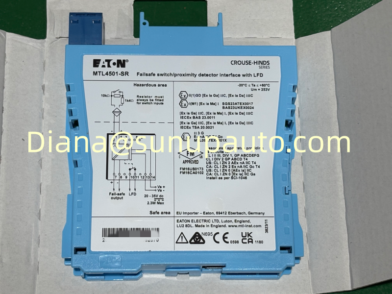
- Confirm the exact MTL4541A model and photograph the received label, packaging, and connector condition.
- Identify the transmitter's independent power source and verify its approved voltage and grounding arrangement.
- Compare field and safe-area terminal assignments with the current loop drawing and backplane schedule.
- Measure supply voltage and loop current before connection, then repeat with the channel operating at several test points.
- Apply approximately 4 mA, 12 mA, and 20 mA and compare the transmitter reference with the control-system value.
- Check under-range and over-range behavior if those values are used for maintenance or diagnostic alarms.
- Verify HART communication, device identity, range, status, and write protection without changing approved parameters.
- Restore covers, labels, shields, forces, and bypasses, then save the as-left test results in the loop record.
Diagnosing Common Field Symptoms
Zero current: check the transmitter power supply, fuse, polarity, cable continuity, backplane power, and receiving input. A passive input cannot energize an unpowered transmitter.
Current stops below full scale: measure the field-device terminal voltage at high current and recalculate the loop resistance. Excessive cable resistance or an added series load may leave insufficient compliance voltage.
Analogue value correct but HART unavailable: confirm the communication terminals, loop impedance, modem connection, shielding, and device HART setting. Compare the problem channel with a working MTL4541A channel on the same backplane.
Stable offset: isolate the error by measuring current at the transmitter, isolator input, isolator output, and control-system reading. This separates transmitter calibration, MTL4541A transfer, wiring, and receiving-card scaling.
Safety, Documentation, and Purchasing Information
Eaton identifies the related MTLx541A family for functional-safety applications, with suitability depending on architecture, failure detection, proof testing, and the complete safety lifecycle. A module rating does not establish the integrity of the full loop. Confirm certificates, intrinsic-safety parameters, field-device approval, cable capacitance and inductance, gas group, temperature class, backplane details, and project requirements using current controlled documents.
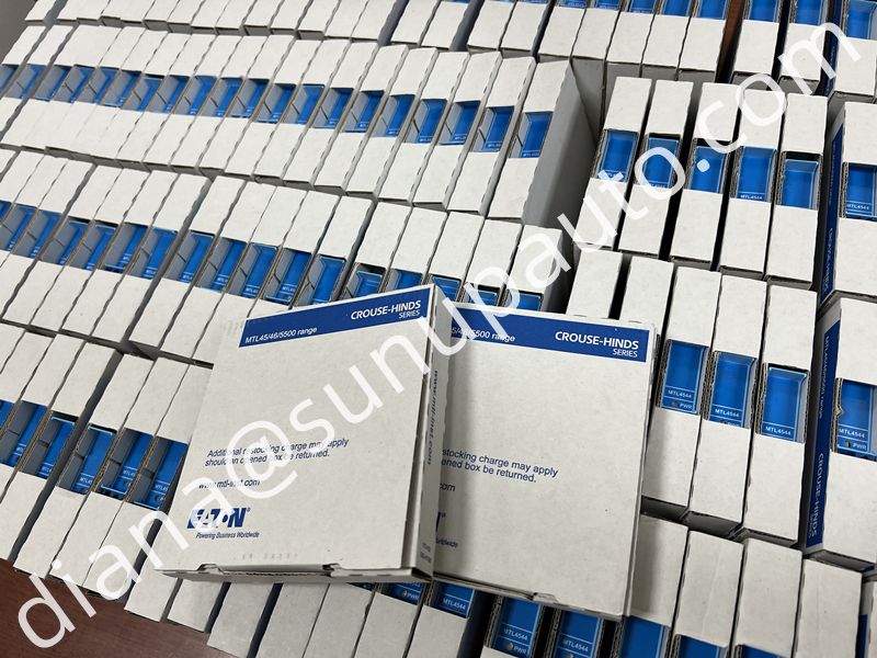
For an MTL4541A inquiry, provide the exact model, quantity, destination country, required delivery date, backplane model, transmitter type, and a clear label photograph. State that the requirement is for the passive-input A variant and whether HART communication must be supported. Sunup-MTL can assist with model confirmation, quotation, protective packing, export documents, and international shipment. Final engineering approval, installation, loop testing, and safety validation remain the responsibility of qualified personnel.