Lifecycle Guide to the Eaton MTL5541 One-Channel HART Repeater Power Supply
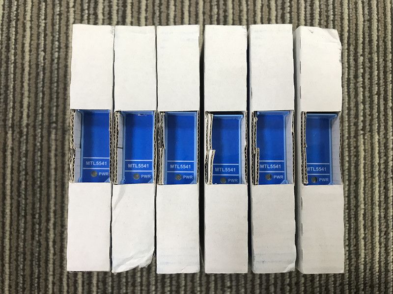
Eaton MTL5541 is a one-channel DIN-rail repeater power supply that energizes a two-wire or three-wire 4-20 mA transmitter in a hazardous area and repeats the measured current to a safe-area control load. It supports HART communication on the designated field terminals and provides galvanic isolation between field, safe-area, and supply circuits. The module is widely suited to pressure, flow, level, temperature, and analytical loops where dependable transmitter power, accurate current transfer, and accessible maintenance diagnostics are required.
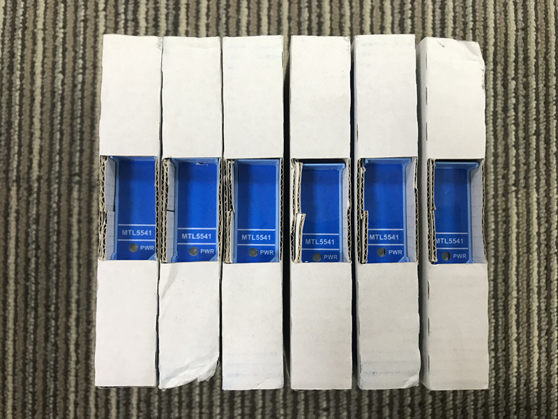
Before Installation: Confirm What the Loop Expects
MTL5541 supplies conventional two-wire or three-wire transmitters. It should not be confused with the MTL5541A passive-input version or the MTL5541S current-sink output version. Begin by identifying the field transmitter wiring and the safe-area analogue input. A two-wire transmitter uses the same conductors for power and signal. A three-wire device has a separate supply relationship. The standard MTL5541 safe-area output drives current into a passive receiving load.
Record the transmitter model, measurement range, loop polarity, terminal numbers, receiving-card type, and HART requirement. Verify the MTL5541 supply source is within the published 20 to 35 V DC range. Check whether the loop participates in an alarm, trip, custody calculation, or environmental report, because the acceptance depth should match the process consequence.
Transmitter Power and Safe-Area Load Must Share the Voltage Budget
The field output must provide enough voltage for the transmitter across the full current range and expected cable resistance. At the safe-area side, the MTL5541 must also drive the receiving load. Eaton lists load guidance up to 360 ohms at 24 mA and up to 450 ohms at 20 mA under the specified conditions. Actual installations may include analogue input resistance, indicators, recorders, surge protection, fuses, and test resistors.
Calculate the loop at minimum DC supply voltage and maximum operating current. Measure the voltage at the MTL5541 and transmitter while simulating a high process value. If a loop reads correctly at 4 mA but cannot reach 20 mA, excessive load, low supply voltage, cable resistance, or a transmitter compliance limit is more likely than a simple calibration error.
Cabinet power also deserves attention. Eaton gives a typical current-consumption reference of 51 mA at 24 V and power dissipation around 0.7 W at 24 V for MTL5541. Multiply the demand across the full module group, include starting and fault conditions, and check enclosure temperature near the most densely populated section.
During Commissioning: Prove the Analogue Path First
Use a calibrated source or the transmitter's approved simulation method to apply several current values. Compare current at the field loop, MTL5541 output, receiving card, and displayed engineering value. Eaton publishes transfer accuracy better than 15 microamps and temperature drift below 0.8 microamps per degree C. The complete installed uncertainty also includes transmitter calibration, test equipment, cable, terminals, receiving-card accuracy, environmental effects, and control-system scaling.
A good three-point test uses approximately 4 mA, 12 mA, and 20 mA. Add under-range and over-range values if the control system uses them for diagnostic alarms. Record both measured current and displayed process units. This makes it possible to identify whether an error comes from current transfer or from range conversion in the control system.
Then Verify HART Without Disturbing the Approved Configuration
MTL5541 supports bidirectional HART communication on terminals 1 and 2. Connect the approved communicator or host, read the transmitter tag, manufacturer, device type, range, units, damping, status, and diagnostic messages, then compare the values with the instrument record. Do not write configuration simply to prove communication. Changes should follow the plant approval and backup process.
If the 4-20 mA signal is stable but HART cannot connect, check loop impedance, modem placement, field-terminal selection, shielding, grounding, electrical noise, and transmitter polling address. HART communication can fail while the analogue measurement remains accurate. Comparing the affected channel with a healthy MTL5541 on the same rail can quickly separate host and field problems.
DIN-Rail Installation Details That Affect Reliability
MTL5541 uses the slim MTL5500 format and mounts on a 35 mm DIN rail. Keep hazardous-area and safe-area wiring segregated, use the correct removable connectors, and protect terminals from conductor strain. Check wire size, ferrules, terminal torque, enclosure ingress protection, ambient temperature, vibration, and ventilation.
The module's green LED confirms power, but it does not prove that the transmitter is powered correctly or that the output current reaches the controller. Treat LED state, measured supply, field current, output current, and process indication as separate checks. Label the module with the loop tag so technicians do not have to trace conductors during an urgent shutdown repair.
Long-Term Maintenance Based on Observable Symptoms
No signal and no power LED: check the 20 to 35 V DC source, fuse, distribution wiring, and terminal polarity before replacing MTL5541.
Power LED on but zero current: inspect the transmitter loop for an open circuit, reversed polarity, failed transmitter, loose connector, or incorrect two-wire/three-wire connection.
Current is noisy: compare field and safe-area measurements, inspect shield termination, grounding, moisture, cable routing, transmitter stability, and nearby switching equipment. Trend data can show whether noise follows process operation or cabinet activity.
Displayed value is wrong but current is correct: check control-system range, engineering units, square-root extraction, signal characterization, and input-card calibration.
Repeated failures in one cabinet: investigate DC supply quality, heat, vibration, connector condition, and grounding. Several apparent module failures may share one environmental or distribution cause.
Replacement Workflow for Minimum Process Risk
- Identify the exact MTL5541 and confirm that no A, S, T, or other suffix is required.
- Photograph labels, connectors, conductor colors, shields, and the existing loop indication.
- Coordinate isolation, alarm suppression, and process permits with operations.
- Verify the replacement module, terminal condition, and certification before installation.
- Reconnect one conductor at a time against the approved drawing and perform a pull check.
- Measure supply, field current, and safe-area output at several operating points.
- Confirm HART access and compare transmitter identity with the loop record.
- Remove all forces and bypasses, then obtain an independent normal-operation check.
Functional Safety and Documentation Discipline
Eaton lists MTL5541 for functional-safety applications, subject to the safety manual, architecture, failure detection, proof-test coverage, and complete instrumented function. The loop's achieved integrity depends on the transmitter, MTL5541, logic solver, final action, wiring, diagnostics, maintenance, and management of change. Preserve the safety requirement, proof-test procedure, test results, and any detected failure in the equipment history.
Intrinsic-safety approval must also be checked for the complete loop. Confirm field-device certification, entity parameters, cable capacitance and inductance, gas or dust group, temperature class, ambient conditions, and associated apparatus certificate. Do not reuse a calculation from another transmitter without confirming every parameter.
Information to Include With an MTL5541 Inquiry
Provide MTL5541, quantity, destination country, required delivery date, condition requirement, and a readable label photo. Mention transmitter type, HART requirement, safe-area input, and whether connectors or related MTL5500 modules are needed. Sunup-MTL can support model checking, quotation, export packing, documents, and international shipment. Final compatibility, loop calculations, installation, configuration, and acceptance testing should follow current Eaton information and the approved plant standard.