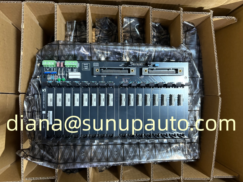
MTL CCY-RS-DO16A-AKB Interface Hardware for a Defined Digital Output System Configuration
MTL CCY-RS-DO16A-AKB is a project-specific interface reference associated with a sixteen-channel digital output arrangement. Components of this type are used to organize connections between control-system I/O, interconnecting cables, power distribution, and MTL interface modules. The exact printed code is therefore the most important starting point for replacement or spare-part purchasing.
Start With the Cabinet, Not With Assumptions
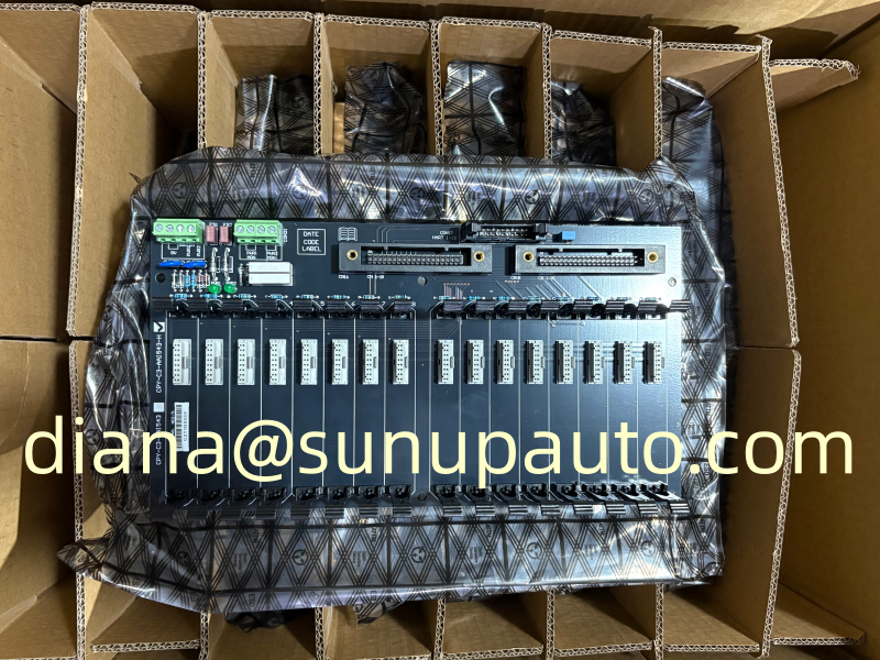
System-interface backplanes can look similar while differing in I/O function, connector assignment, cable type, supported modules, redundancy arrangement, or left- and right-hand cabinet orientation. For CCY-RS-DO16A-AKB, the safest method is to compare the complete label with the approved panel drawing and the bill of materials. Do not substitute a part based only on “DO16” or the appearance of the board.
Eaton documentation for related MTL interfaces shows dedicated sixteen-channel digital-output backplanes for Yokogawa ProSafe-RS architectures, with AKB-series redundant cable connections and specific MTL4500 interface modules. That system context is useful for identification, but the exact CCY-RS-DO16A-AKB configuration must still be confirmed from the installed hardware and project documentation before ordering.
Five Records That Make Replacement Work Easier
- Label record: photograph every model, revision, serial, and connector marking.
- I/O record: identify the control-system card and confirm the sixteen-channel digital-output function.
- Cable record: note both ends of the AKB cable, connector orientation, and redundancy arrangement.
- Module record: list each installed MTL module and its channel position.
- Project record: retain the cabinet drawing, wiring schedule, loop references, and approved change history.
Receiving and Installation Review
When CCY-RS-DO16A-AKB arrives, compare the label and physical connectors with the purchase order before it enters site stock. Inspect the board, guides, terminals, and packaging for transport damage. Installation should be completed during an approved maintenance window with power isolation, electrostatic-discharge controls, wiring verification, channel tests, and documented functional checks.
For a quotation, send the exact CCY-RS-DO16A-AKB code, quantity, destination, required date, product condition requirement, and clear photographs of the installed item. Sunup-MTL can assist with international sourcing and combined MTL spare lists, while final technical approval remains with the system owner and qualified project engineers.
What a System Interface Backplane Contributes
A dedicated interface backplane replaces large amounts of point-to-point cabinet wiring with a repeatable connection structure. In a sixteen-channel digital-output arrangement, it can distribute system-side signals, module connections, common power, and cable interfaces in an organized assembly. This approach can reduce wiring time, improve channel identification, and make module replacement more consistent across cabinets built to the same design.
The benefit depends on using the exact backplane, cable, I/O card, and MTL modules specified by the project. Connector keying alone should not be treated as proof of compatibility. Similar assemblies may route signals differently or support different diagnostic and redundancy functions.
Confirm the Printed Code Character by Character
The requested reference is CCY-RS-DO16A-AKB. Related Eaton literature includes CPY-RS digital-output interfaces for Yokogawa ProSafe-RS systems, and codes may contain characters that are easily confused in photographs, including C and P, O and zero, or similar suffixes. The product label, project bill of materials, and wiring drawing must therefore be compared character by character before purchase. If the label is unclear, provide a high-resolution photograph of the complete assembly and its connectors rather than relying on a manually typed description.
The suffix can identify cable or system details that are essential to correct operation. Do not shorten CCY-RS-DO16A-AKB to a generic “16-channel output backplane” when requesting a replacement. A generic description may return several products that perform different functions.
Trace One Digital Output From System to Field
A practical compatibility review follows one complete channel. Start at the control or safety-system output card, identify the system cable and connector, trace the assigned backplane channel, record the fitted MTL interface module, and continue through the field terminals to the final load. Repeat the check for the first and last channels and any channels with special wiring. This process confirms channel numbering, common connections, power distribution, and whether redundancy or line-fault functions are present.
The final load may be a solenoid valve, relay, alarm device, or another controlled circuit. Its voltage, current, hazardous-area classification, and failure action must be compatible with the selected interface module and system design. The backplane itself should not be used to infer those details without supporting drawings.
Installation and Commissioning Checklist
- Isolate and verify all relevant power sources according to the site procedure.
- Use electrostatic-discharge protection when handling the board and connectors.
- Compare mounting dimensions, connector orientation, keying, and cable length with the removed unit.
- Inspect pins, guides, terminal blocks, fuses, and power connectors before installation.
- Confirm primary and redundant cable connections against the approved drawing.
- Install modules in the documented channel positions and verify their complete part numbers.
- Energize in a controlled sequence and check supply voltage, alarms, and system diagnostics.
- Function-test every affected output, including its defined safe and de-energized states.
Digital outputs may operate important final elements, so commissioning must be coordinated with operations and process-safety personnel. Prevent unintended valve movement or equipment start-up during testing. Any temporary force, bypass, or inhibited trip should be logged and cleared before the system is returned to normal service.
Documentation, Change Control, and Spares
Update the cabinet drawing, cable schedule, channel list, module schedule, and spare-parts register after replacement. Record the received model, revision, serial information, installation date, and test results. If the replacement differs from the original revision, obtain engineering approval and document the reason for the change. Keeping this information with the system prevents the same identification problem during the next maintenance event.
For a CCY-RS-DO16A-AKB inquiry, send the complete code, quantity, clear front-and-rear photographs, associated I/O card, installed MTL modules, cable references, destination, and required delivery date. State whether the item is needed for urgent failure replacement, a planned shutdown, a project expansion, or warehouse stock. Sunup-MTL can support sourcing and shipping coordination, while the owner remains responsible for final compatibility approval and functional-safety requirements.