Eaton MTL CPY-C3-RAI141 Backplane for Redundant Yokogawa Analog Input Integration
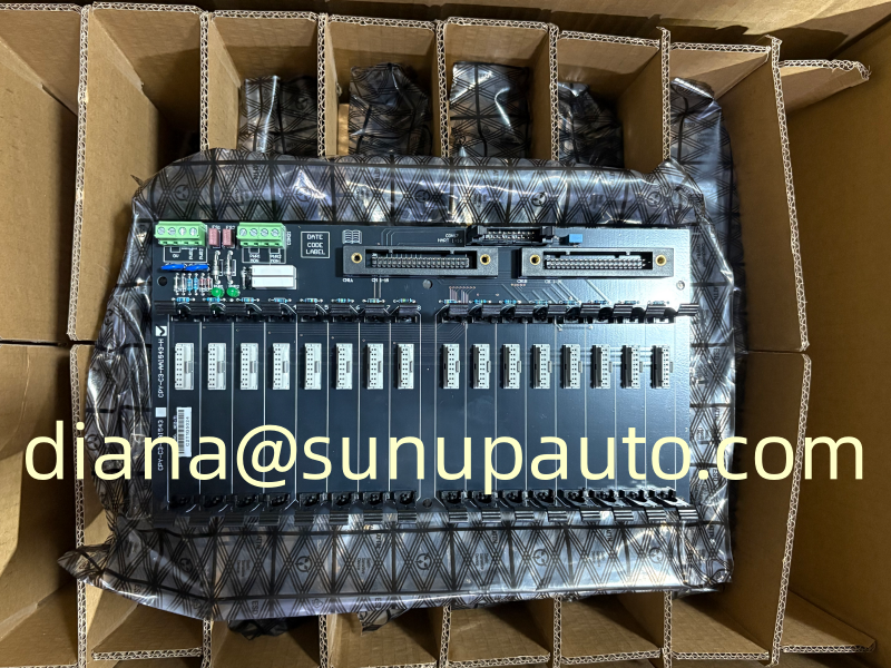
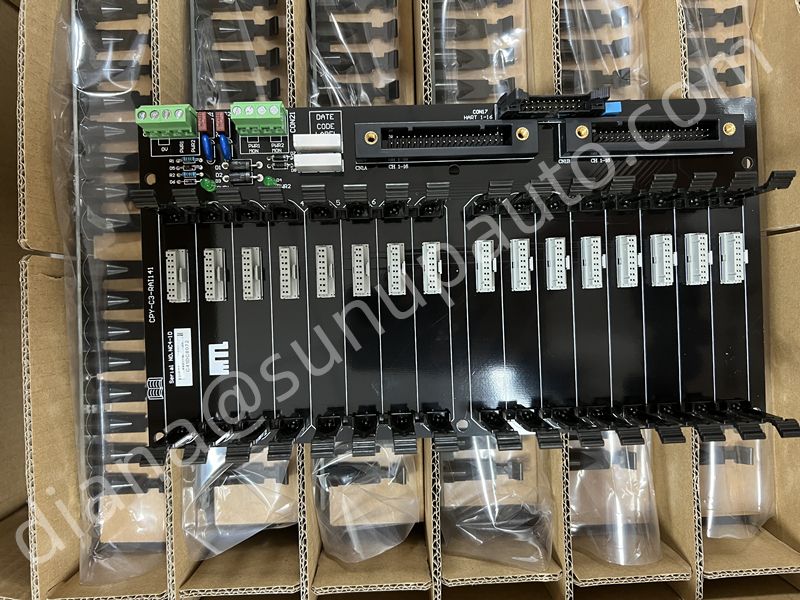
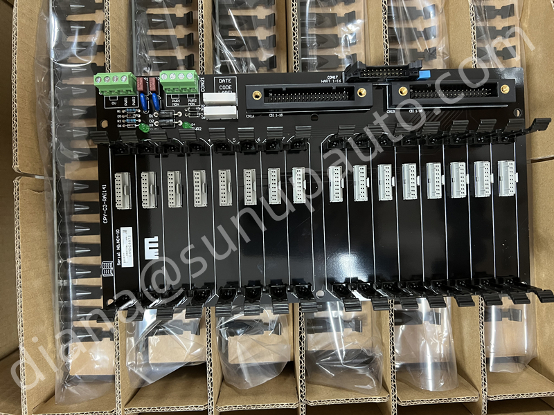
CPY-C3-RAI141 is a dedicated system interface backplane for connecting selected Yokogawa CENTUM VP or ProSafe-RS analog input hardware with MTL4500 intrinsically safe interface modules. The assembly provides sixteen 4-20 mA analog input channels and supports a redundant system connection through KS1x2 cable arrangements. CPY-C3-RAI141 is intended for engineered cabinet integration, so the complete system architecture matters as much as the model printed on the board.
How CPY-C3-RAI141 Fits the System
CPY-C3-RAI141 is a sixteen-channel 4-20 mA analog input backplane developed for defined Yokogawa system arrangements. It is commonly associated with CENTUM VP or ProSafe-RS architectures, but the exact I/O card, cable, module population, and redundancy design must follow the approved project documents.
- Control-system side: project configurations may reference AAI141(-H) or AAI143(-H) analog input hardware.
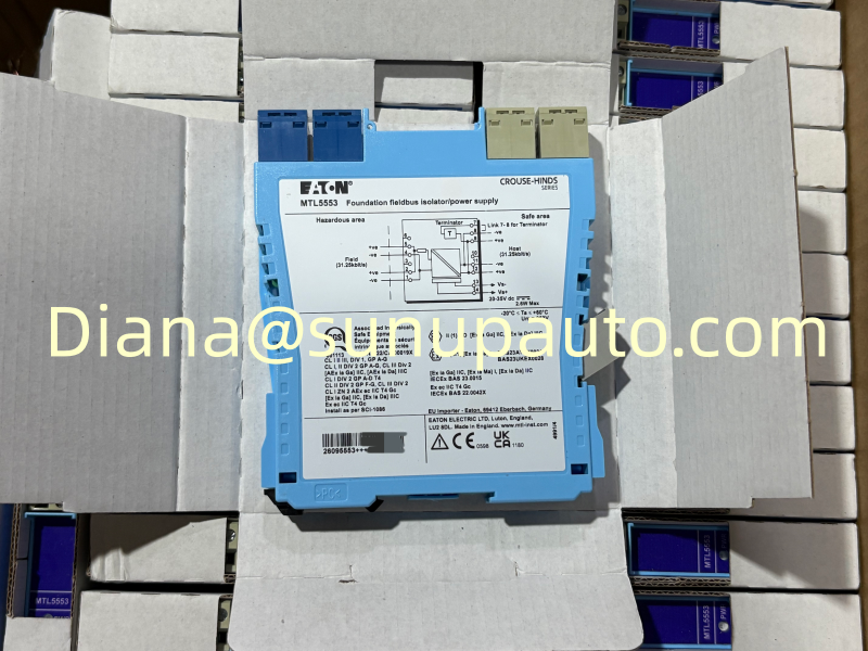
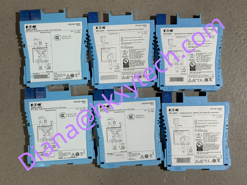
- Interface-module side: the backplane can be arranged with MTL4541 or MTL4575 modules across as many as sixteen positions, according to the required field-loop function.
- System connection: KS1x2 cable references and a redundant connection concept are part of the documented architecture.
These relationships make the full model number important when ordering a spare. Before selecting CPY-C3-RAI141, compare the installed label, backplane revision, Yokogawa I/O designation, MTL module type, cable part number, connector orientation, power arrangement, and channel schedule. Similar-looking assemblies should not be treated as interchangeable without an engineering review.
Why a Dedicated Backplane Is Used
A traditional cabinet may wire every safe-area isolator output separately to a DCS terminal block. CPY-C3-RAI141 creates a structured connection between the MTL modules and Yokogawa I/O, reducing individual wires and providing repeatable channel routing. The backplane also organizes module positions, system cables, power distribution, and cabinet identification in one assembly.
Reduced wiring can save panel space and commissioning time, but it also increases the importance of exact compatibility. A visually similar backplane may use another channel count, I/O function, cable arrangement, or MTL module family. Always verify CPY-C3-RAI141 from the approved bill of materials and connection drawings.
Follow One Channel Through the Architecture
A useful design review starts at the hazardous-area transmitter. The 4-20 mA signal enters the field side of an MTL4541 or compatible module. The isolator supplies or receives the loop current and transfers the safe-area signal into the CPY-C3-RAI141 routing. From the backplane, a KS1 cable carries the channel group to the designated Yokogawa analog input module. The redundant connection provides the second system path defined by the project.
Repeat this trace for the first, middle, and last channels. Confirm that channel numbering remains consistent at the field terminals, MTL slot, backplane, cable connector, I/O card, and DCS database. A single numbering offset can place a valid process value under the wrong tag.
Redundancy Requires More Than Two Cables
A redundant design is only useful when the two paths are correctly connected, configured, powered, and tested. Review the Yokogawa I/O pairing, cable references, connector orientation, power feeds, grounding, and diagnostic behavior. Where practical, route redundant cables so one physical event is less likely to damage both. Label each end clearly and preserve the project naming convention.
Commissioning should demonstrate the expected system response to loss of one path without creating an uncontrolled process disturbance. Tests must be coordinated with control and safety personnel, and every temporary bypass or inhibited alarm must be cleared afterward.
Cabinet Installation Review
- Confirm mounting dimensions, orientation, ventilation, and access for module removal.
- Verify all primary and redundant power connections and protective devices.
- Inspect system connectors and use only the specified KS1 cable assemblies.
- Check earth rails, screen termination, intrinsic-safety segregation, and field terminal identification.
- Install only the MTL module types assigned by the project documentation.
- Protect unused connectors and prevent loose hardware from entering the backplane.
- Apply electrostatic-discharge controls during handling and installation.
Commissioning and Receiving Checks
Before energizing CPY-C3-RAI141, verify the model, revision, cable orientation, module positions, and supply polarity. Apply controlled current signals to representative channels and confirm the corresponding DCS tags. Then expand testing to all sixteen positions according to the project procedure. Record zero, midpoint, and span checks where required, together with redundancy and diagnostic results.
On receipt, inspect CPY-C3-RAI141 for bent pins, cracked guides, damaged connectors, contamination, or impact to the board. Compare the supplied accessories and connector assemblies with the purchase order. Keep antistatic packaging until the unit reaches the panel shop or site.
Information for an Accurate Inquiry
Provide the complete CPY-C3-RAI141 code, quantity, destination, required delivery date, associated Yokogawa I/O module, MTL module list, cable requirement, and cabinet drawing reference. State whether the order is for a new project, expansion, shutdown spare, or urgent replacement. Sunup-MTL can coordinate model checking, packing, documentation, and international shipping. Final system compatibility, redundancy design, intrinsic-safety assessment, installation, and commissioning remain the responsibility of qualified project personnel.
Loop Acceptance Across All Sixteen Channels
A sample test can confirm the general design, but final acceptance should account for every populated position. Prepare a channel sheet showing field tag, MTL module model, backplane slot, cable path, Yokogawa channel, DCS tag, engineering range, and alarm references. Inject a known current at the approved point and confirm that only the intended database point changes. Where HART or transmitter power is involved, test those functions separately. Sign off each channel only after identification, polarity, scaling, and diagnostics are correct.
If a channel fails, swap tests should be planned carefully. Moving a known good module can help distinguish the module from the backplane position, but it can also disturb another commissioned loop. Use spare modules or a controlled maintenance window, document every movement, and restore original positions before comparing results. Inspect connector pins with adequate lighting; a bent contact can create an intermittent problem that disappears when the cabinet door is open.
Spare Backplane Strategy
A CPY-C3-RAI141 spare should be stored with compatible cable and connector information, not as an unidentified circuit board. Record which plants and cabinet revisions it supports. Protect it from electrostatic discharge, humidity, dust, and mechanical bending. For critical facilities, a periodic visual inspection and controlled fit check can reduce the risk of discovering missing accessories during an emergency shutdown.
Keep the original drawings and a tested channel schedule available offline. If a server or engineering workstation is unavailable during a plant incident, maintenance teams should still be able to identify the redundant paths and restore the backplane safely. This documentation is as important as the physical CPY-C3-RAI141 spare.