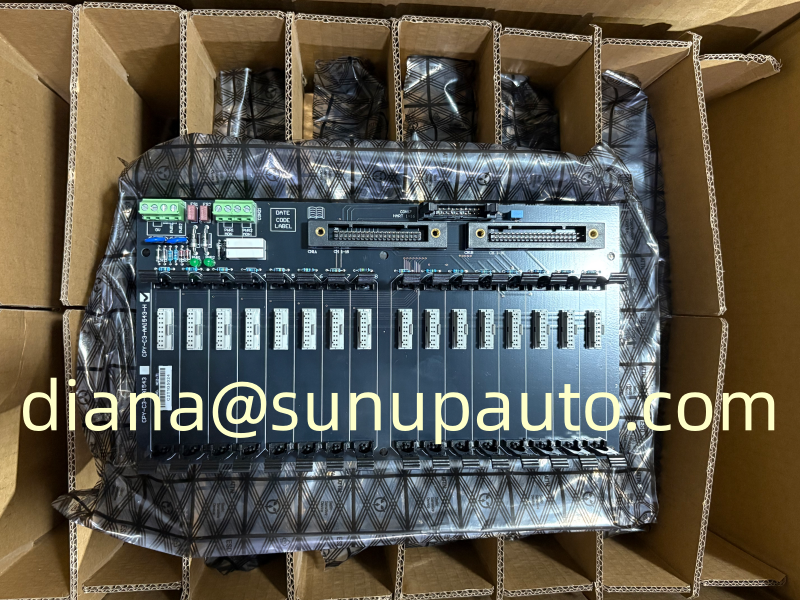
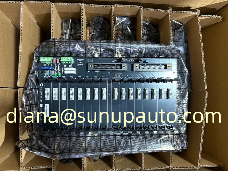
Eaton MTL CPY-C3-AAI543-H Backplane for Redundant Yokogawa Analog Output and MTL4546Y Interface Systems
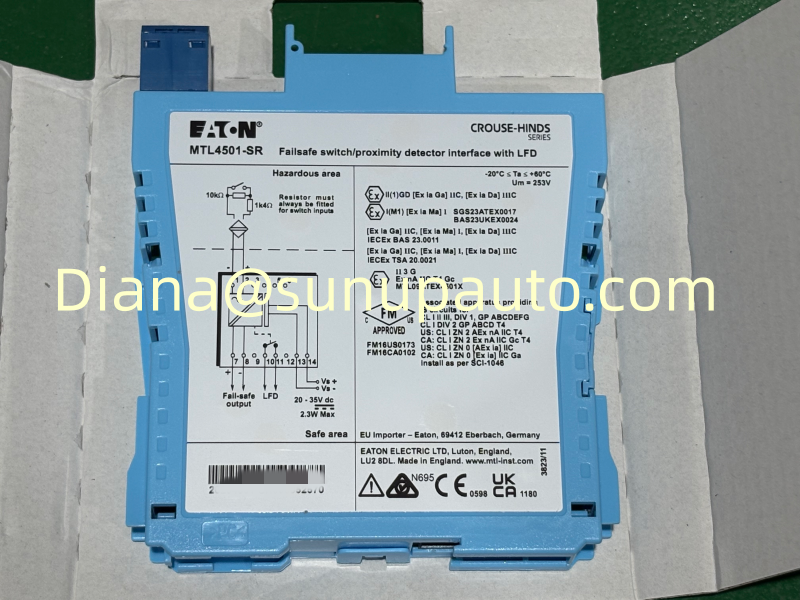
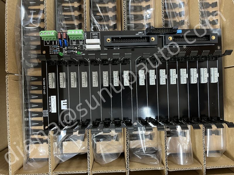
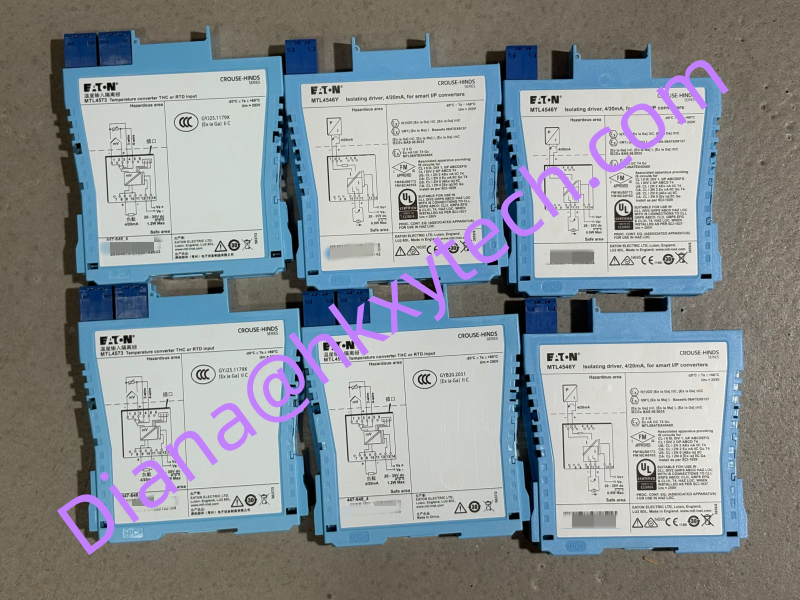
CPY-C3-AAI543-H is a dedicated sixteen-channel analog output backplane for integrating the Yokogawa AAI543-H I/O module with MTL4500 intrinsically safe isolating drivers. Eaton system literature identifies MTL4546Y modules in all sixteen positions, a KS1x2 cable arrangement, and a redundant system connection. The backplane is used where control commands must travel from the safe-area control system toward hazardous-area final elements such as valve positioners or current-operated devices.
The Signal Journey From Controller to Final Element
An analog output channel begins with a command calculated by the control or safety system. The Yokogawa AAI543-H converts that command into the system-side electrical signal. The KS1 cable carries the channel group to CPY-C3-AAI543-H, where each channel is routed to its assigned MTL4546Y isolating driver. The MTL module then transfers the 4-20 mA command to the hazardous-area field loop within the approved intrinsic-safety parameters.
The complete path must preserve channel identity, current accuracy, fault indication, and the defined response to loss of power or communication. CPY-C3-AAI543-H is therefore part of an engineered system rather than a general terminal board.
System Identification at a Glance
CPY-C3-AAI543-H is designed as a dedicated interface point for a redundant Yokogawa analog output arrangement. In the typical documented configuration, it connects an AAI543-H control-system I/O module to a bank of MTL4546Y interface modules, helping organize sixteen 4-20 mA output channels within one coordinated cabinet assembly.
- Interface role: sixteen-channel analog output backplane for sending controller commands toward field devices.
- Typical module arrangement: Yokogawa AAI543-H with sixteen MTL4546Y interface modules.
- Connection concept: KS1x2 system cable arrangement with a redundant architecture.
These identifiers are useful for model confirmation and quotation, but the final CPY-C3-AAI543-H configuration should always be checked against the cabinet drawings, Yokogawa hardware revision, cable schedule, hazardous-area documentation, and the approved project bill of materials.
Why Analog Output Testing Needs Process Coordination
An analog input test observes a measurement, but an analog output test can move equipment. Forcing 4 mA, 12 mA, or 20 mA may close a valve, increase speed, change heater demand, or alter another process condition. Every CPY-C3-AAI543-H commissioning activity must be coordinated with operations. Isolate the final element, use a simulator, disconnect the actuator, or apply another approved method so the test cannot create an unintended plant response.
The test procedure should define the safe state, required permits, communication with the control room, temporary overrides, and restoration steps. All forces and bypasses must be removed and independently checked before normal service resumes.
Channel-by-Channel Commissioning
- Verify the CPY-C3-AAI543-H label, revision, orientation, and physical condition.
- Confirm that the specified AAI543-H, KS1 cables, and sixteen MTL4546Y modules are installed in the documented positions.
- Check power feeds, grounding, connector seating, intrinsic-safety segregation, and field-terminal labels.
- Select channel 1 and apply controlled output commands while measuring field-loop current with an approved method.
- Compare commanded value, module output, loop current, and final-element indication at low, middle, and high points.
- Repeat the identity check across all channels, paying particular attention to the last channel and connector boundaries.
- Test system diagnostics, line-fault response, and the designed redundant-path behavior.
- Return every channel to automatic control and document the as-left status.
Redundant Cable and Power Considerations
The redundant arrangement should be verified against the Yokogawa system design. Confirm primary and secondary system paths, cable destination, connector keying, diagnostic handling, and any shared power dependencies. Two cables do not create useful redundancy if they are connected to the wrong pair, routed through the same vulnerable location, or supported by one undocumented power source.
Perform redundancy tests under controlled conditions. Observe alarms and output behavior during the simulated loss of each path. The acceptable response depends on the application, controller configuration, and final-element fail position. Record the test outcome rather than relying on a simple visual inspection.
Replacement Without Losing Channel Mapping
Before removing CPY-C3-AAI543-H, photograph every connector and label. Export the channel schedule, mark both ends of the KS1 cables, record module positions, and confirm which field loops can be isolated. Where the old backplane has a fault, distinguish board damage from a failed MTL4546Y, cable problem, I/O-card issue, or power-supply fault. Replacing the backplane without identifying the cause may leave the original problem unchanged.
During receiving inspection, compare the complete part number and revision, inspect pins and guides, and verify supplied connectors and accessories. Store the board in antistatic packaging and controlled environmental conditions until installation.
Engineering Records and Purchasing Details
Keep the CPY-C3-AAI543-H bill of materials, wiring diagram, channel list, cable schedule, redundancy drawing, test sheets, and spare-parts record together. Update the documents after any approved revision. Clear records reduce troubleshooting time and prevent accidental use of a similar analog-input or higher-density backplane.
For purchasing, provide CPY-C3-AAI543-H, quantity, destination country, delivery deadline, Yokogawa I/O reference, MTL4546Y requirement, KS1 cable requirement, and any documentation or packing needs. Sunup-MTL can assist with combined backplane, module, and cable inquiries for project and maintenance supply. Final compatibility, intrinsic-safety review, system configuration, commissioning, and functional-safety approval must be completed by qualified engineering personnel.
Reviewing Output Failure Modes
For every CPY-C3-AAI543-H channel, define what happens if system power is lost, one redundant path fails, an MTL4546Y is removed, the field cable opens, or the final element loses air or auxiliary power. The electrical current may move upscale, downscale, hold briefly, or collapse depending on the surrounding system. The mechanical final position is also influenced by the actuator and process design. Document these outcomes in the cause-and-effect or control narrative so maintenance teams know which observations are expected.
Line-fault diagnostics should be tested with the actual system configuration. An open field loop, short circuit, disconnected module, and failed cable may create different alarms. Verify that the operator message identifies the correct channel and that maintenance diagnostics point to the appropriate cabinet. Where the output participates in a shutdown or protective function, include the backplane and interface modules in the proof-test strategy.
Typical Project Uses
CPY-C3-AAI543-H may be used for groups of control valves, pressure regulators, variable-speed references, damper commands, dosing controls, and other 4-20 mA outputs in oil and gas, chemical, power, water, refining, pharmaceutical, and marine projects. Grouping sixteen channels on one backplane supports compact cabinet design, but it also concentrates several process commands in one assembly. Good labeling, spare planning, redundancy testing, and controlled access are therefore essential.
For brownfield expansion, compare the new channel demand with available AAI543-H capacity, cabinet space, backplane power, cable routes, and MTL4546Y inventory. Confirm that the control-system software, hardware revision, and project standards support the addition before procurement begins.